I had an abbreviated work day on Sunday but did get a few key tasks accomplished. I didn't take any pictures today, making this a text only posting.
CORE MEMORY REPAIRS
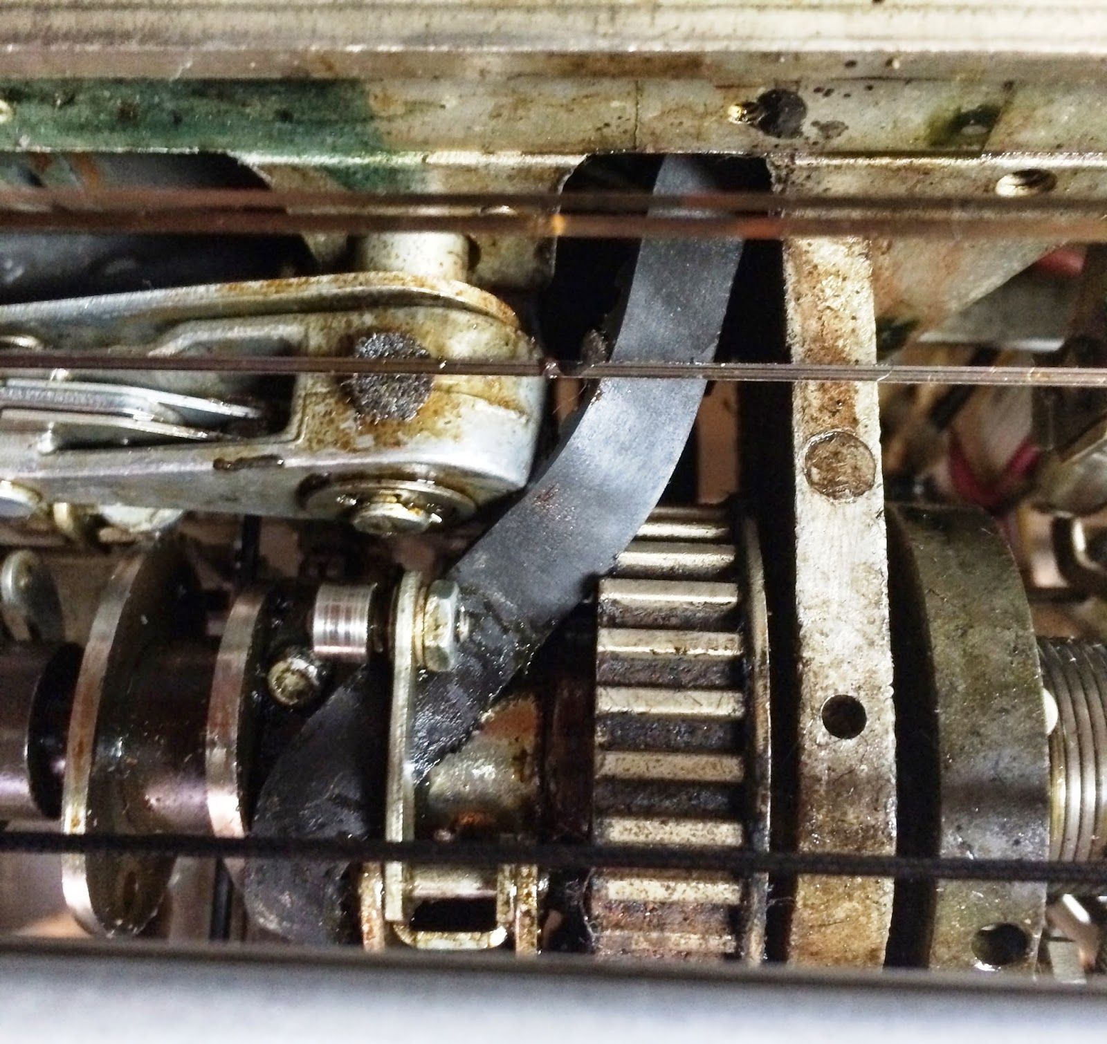
Having definitively identified the bad card causing the parity errors in the first 8K of memory, and temporarily booting the problem up to high memory by swapping cards between compartments, I then had to determine enough about the errors in high memory that I could know the bad part and work out a fix. This involved trying various loads and stores and many addresses in the upper 8K to find what were the fixed conditions that produced the problem.
There is one problem for addfresses of the form xx11 00xx xxxx xxxx due to the bad card I swapped into place - it means that no read occurs for any words in the 1K of memory beginning at that address. However, I was also shooting the problem of the 1 and 5 bits that always come back as being on, even though they were stored as zeroes.
I determined that this occurred in any address in the upper 8K, which is peculiar because there are virtually completely independent cards and wiring paths for each 4K half of the memory. I would have to believe that two cards, side by side, both failed in exactly the same way, if I were to trace this to a failing SLT card.
I checked power supplies, looked at physical conditions on the backplane and did lots of deep thinking to try to spot anything that could cause this problem for both. I am still stumped, although it could be a failure in a ribbon cable connecting the two storage compartments together.
I tried to scope the problem but didn't really get a good reading on the issue from that. I decided to swap cards around - the inhibit/sense cards for bits 1 & 5, at A4 and B4, work on the upper and lower half of memory respectively. I swapped them with their peers a row above, in A3 and B3, which control the 7&9 bits. The problem did not move with the cards, which supports my suspicion that the problem is not related to those cards. The sense and inhibit lines in the core stack itself are independent for the two 4K halves.
The signal to inhibit bit 1 and 5 come in via a cable from the other (low 8K) compartment, and are passed to a pair of cards which send the signal to their respective half of memory. If it were a card problem, it would mean a pair of cards with the exact same error.
Furthermore, when I powered up later and tried some code, I found that the 1&5 bit contagion had spread to the lower 8K of memory. That certainly sounds like cabling or a short on that part of the backplane. I didn't touch any cards in the low 8K compartment.
1132 PRINTER RESTORATION
The 1132 does emit characters, respond to all the XIO commands and even prints in the right columns when I ask it to. The only issue is that somehow I am printing the wrong characters. this could be a timing issue with the encoder wheel in the printer, a defect in the cycle stealing circuitry, or a defect in my hand entered program. I would bet on the last as the cause, but I will need to get the memory working again before I can fix and rerun the program.
Sunday, August 31, 2014
Saturday, August 30, 2014
First 8K of memory now working perfectly, plus other progress on 1132, 1442, and 1053 - Aug 30, 2014
PROGRESS ON FIXING PROCESSOR CORE MEMORY
I went through voltage verification and other tests first to be sure core is within its proper supply range and adjusted right.I found a few of the logic voltages just a bit out of spec, so I got serious about adjusting my voltage regulators. I wanted an extremely accurate meter, since the specs for some of the voltages require it to be less than half a percent.
I borrowed one from our restoration team workroom at the Computer History Museum and made sure my main logic voltages, +3V, -3V and +6V, were as close to perfect as I could tweak them. The 12V and 48V voltages don't have adjustable regulators, instead relying on ferroresonant transformers, but were well within spec as they were.
The issues were exactly as before, but I had ruled out voltage supply problems. My diagnosis a few days ago was that the parity errors I was getting in the first 8K of memory were caused by a failed circuit on a 5803467 SLT card (also referred to as 3467) sitting in the H3 card slot of B1 compartment of D gate. To confirm, I did some swapping of this 3467 card with others in the same compartment. When I swapped it with the K3 slot, the failure symptoms changed exactly as they should if the card were at fault. Now, addresses of the form xxxx xx10 0xxx xxxx receive parity errors.
To further confirm, I moved the bad card to the M3 slot, which would move the error to address patterns of xxx1 00xx xxxx xxxx and that was exactly what happened! My final swap was to swap the cards in M3 slots of the two compartments, A1 and B1. That moved the failure up to the high 8K of memory. I verified that the first 8K of memory worked perfectly.
I have a different problem in the high 8K of core - bits that are reading as on even when they were written as zeroes. For example, bit 5 is always a 1 when a word is read, but if may have been intended to be zero, thus storing incorrect parity. On top of that problem I have the bad 3467 card I moved over from the first 8K compartment. I need to do some very thorough testing to define the exact failures and what address ranges they pertain to, in order to identify what portions of the core and what cards are presumably bad. I will do that tomorrow, after perusing the ALDs some more tonight.
1442 CARD READER
I now have my Mobil synthetic grease (Aviation #28) to use on the card reader, printer and typewriter mechanisms. I am working with the lubrication recommendations from the 1442 maintenance manual, but this is a slow process. First, I need to identify what has to be lubricated, when the name they give is not labeled on any diagram and may be a synonym of the name used in the parts catalog. Then it has to have the dirt, dust and old grease removed before I can lubricate it.
The machine sounds better already, even though I am not done lubricating; I only got through about half the moving parts. I still can't get the machine to go into ready state - it has only done that two times out of a few hundred NPRO cycles and pushes of the start button. I am going to have to do some diagnostic testing to be sure where the issue lies - it could be logic or cabling in the 1131, logic or cabling or switch problems in the 1442, or problems with the signal cable linking the two.
When I manually trip the feed clutch, it does nicely feed cards through the preread, read, punch and stacker corner stations. For some reason, cards aren't nudged into the stacker mechanism rollers so they will pile up in the corner station. Cards slid toward the rear of the machine from the input hopper (into the preread station), then move right to left to be read and punched before arriving in the stacker corner. From the left rear corner, the then move forward on the left side and drop into one of the stackers.
1132 PRINTER
I worked out programs to test the printer from the processor - code to space a line and to print a line of type. I used Brian Knittel's 1130 simulator to assemble the code and do testing, so I wouldn't spend too much time toggling in code by the console bit switches and mode switch. I wasn't able to test the actual operation, because the simulator declares the XIO to be an error, although the live machine had no problem with them. Not sure whether it is a limitation of the simulator or some more subtle issue in how it emulates the printer, but I had what I needed to move into the garage and try it out on real hardware.
I powered up the processor toggled in all the code, but then found that the printer wouldn't power up. It was because I had shifted the 1130 slightly on its rollers, which pulled the power cable for the printer out of the socket - due to the missing threaded hole on the socket. I powered down, inserted the power cord, and the printer came up properly.
The first version of the code did a carriage space - move down one line on the paper. Worked perfectly. That is excellent. I know now that the device sees the XIO commands, it decodes them correctly, drives the printer, and provides status on interrupt level 1. The only function this didn't involve was the cycle stealing that the printer does to fetch the fixed eight bytes to fire hammers, nor the character by character interrupts from the print wheel and the read emitter operation that determines which character it was.
The next version of the program should print a line - my first name two times - but the printer gave a printer scan check error. I put this aside to work on later, but tonight I remembered that I have to set a specific bit in the word at the end of the scan area (addresses 32 to 40, last bit of word 40 must be a 1) otherwise the print scan error is given. The program may well have worked.
1053 CONSOLE PRINTER
The cycle clutch latch piece I had removed had a spring attached to it and to a bracket inside the machine, but the spring broke off from the remote bracket. I have comparable springs to replace it, but getting access to the bracket where it attaches is going to be challenging.
I did a bit of greasing with my Mobil 28 and did a power on test of the belt. Under power, the machine continuously does line feeds (indexes) and it continually types a default character (because the cycle clutch latch is not installed yet). All good for the state this is in and where I am in the rehab process that eventually restores full operation of Selectric mechanisms.
The machine has a feature to select black or red ink under program control - using a ribbon that has one color along the bottom and the other along the top. The tape that threads over multiple pulleys to move the ribbon up or down was broken when I got the machine. A friend I have previously worked with on other Selectric based machines is sending me the proper replacement tape from his shop in Switzerland (Lukas Tschudi of TSCHUDI Büromaschinen).
Peter Vaughan of The National Museum of Computing in the UK, who has restored an 1130 in their collection, sent me a wonderful chart that gives modern substitutes for all the mystery IBM lubricants - always referred to simply by a number like IBM #23 or IBM #10. I knew of the equivalence of Mobil Aviation Grease #28 to IBM #23, but this gives me great alternatives for many other types as well.
I went through voltage verification and other tests first to be sure core is within its proper supply range and adjusted right.I found a few of the logic voltages just a bit out of spec, so I got serious about adjusting my voltage regulators. I wanted an extremely accurate meter, since the specs for some of the voltages require it to be less than half a percent.
I borrowed one from our restoration team workroom at the Computer History Museum and made sure my main logic voltages, +3V, -3V and +6V, were as close to perfect as I could tweak them. The 12V and 48V voltages don't have adjustable regulators, instead relying on ferroresonant transformers, but were well within spec as they were.
The issues were exactly as before, but I had ruled out voltage supply problems. My diagnosis a few days ago was that the parity errors I was getting in the first 8K of memory were caused by a failed circuit on a 5803467 SLT card (also referred to as 3467) sitting in the H3 card slot of B1 compartment of D gate. To confirm, I did some swapping of this 3467 card with others in the same compartment. When I swapped it with the K3 slot, the failure symptoms changed exactly as they should if the card were at fault. Now, addresses of the form xxxx xx10 0xxx xxxx receive parity errors.
To further confirm, I moved the bad card to the M3 slot, which would move the error to address patterns of xxx1 00xx xxxx xxxx and that was exactly what happened! My final swap was to swap the cards in M3 slots of the two compartments, A1 and B1. That moved the failure up to the high 8K of memory. I verified that the first 8K of memory worked perfectly.
 |
| D gate (core memory) each compartment is 8K |
1442 CARD READER
I now have my Mobil synthetic grease (Aviation #28) to use on the card reader, printer and typewriter mechanisms. I am working with the lubrication recommendations from the 1442 maintenance manual, but this is a slow process. First, I need to identify what has to be lubricated, when the name they give is not labeled on any diagram and may be a synonym of the name used in the parts catalog. Then it has to have the dirt, dust and old grease removed before I can lubricate it.
The machine sounds better already, even though I am not done lubricating; I only got through about half the moving parts. I still can't get the machine to go into ready state - it has only done that two times out of a few hundred NPRO cycles and pushes of the start button. I am going to have to do some diagnostic testing to be sure where the issue lies - it could be logic or cabling in the 1131, logic or cabling or switch problems in the 1442, or problems with the signal cable linking the two.
When I manually trip the feed clutch, it does nicely feed cards through the preread, read, punch and stacker corner stations. For some reason, cards aren't nudged into the stacker mechanism rollers so they will pile up in the corner station. Cards slid toward the rear of the machine from the input hopper (into the preread station), then move right to left to be read and punched before arriving in the stacker corner. From the left rear corner, the then move forward on the left side and drop into one of the stackers.
1132 PRINTER
I worked out programs to test the printer from the processor - code to space a line and to print a line of type. I used Brian Knittel's 1130 simulator to assemble the code and do testing, so I wouldn't spend too much time toggling in code by the console bit switches and mode switch. I wasn't able to test the actual operation, because the simulator declares the XIO to be an error, although the live machine had no problem with them. Not sure whether it is a limitation of the simulator or some more subtle issue in how it emulates the printer, but I had what I needed to move into the garage and try it out on real hardware.
 |
| Early and incorrect assembly of program to print a line |
The first version of the code did a carriage space - move down one line on the paper. Worked perfectly. That is excellent. I know now that the device sees the XIO commands, it decodes them correctly, drives the printer, and provides status on interrupt level 1. The only function this didn't involve was the cycle stealing that the printer does to fetch the fixed eight bytes to fire hammers, nor the character by character interrupts from the print wheel and the read emitter operation that determines which character it was.
The next version of the program should print a line - my first name two times - but the printer gave a printer scan check error. I put this aside to work on later, but tonight I remembered that I have to set a specific bit in the word at the end of the scan area (addresses 32 to 40, last bit of word 40 must be a 1) otherwise the print scan error is given. The program may well have worked.
1053 CONSOLE PRINTER
The cycle clutch latch piece I had removed had a spring attached to it and to a bracket inside the machine, but the spring broke off from the remote bracket. I have comparable springs to replace it, but getting access to the bracket where it attaches is going to be challenging.
 |
| Broken spring from cycle clutch latch |
 |
| Bit of grease (red color) in the bearing till full |
 |
| Remnant of ribbon shift tape |
 |
| Parts catalog with ribbon shift mechanism parts listed |
Friday, August 29, 2014
Processor, typewriter, card reader and printer work - August 29, 2014
PRINTER RESTORATION CONTINUES
I repaired the screw that tightens the printer power connector into the 1131, by opening the connector body, putting a small cotter pin through the two parts to hold them together and reassembling.First time, I put the threaded bottom in the wrong way - see picture of it protruding too far. I reopened the connector and made it right. All good, apparently, except that the screw still wasn't catching. When I looked at the receptacle, it was missing the threaded hole in the center into which the connector screw attaches.
I could still push the power connector in where it would work properly, as long as the cable didn't get pulled since there is no screw to hold it into place. Since the cables are now attached, I powered up the 1131 and indeed the 1132 printer is now powering up. It initially had a forms check error light on, which just means that no paper is in the printer.
With paper added, the check light went off. The motor power switch got the motor spinning and the ribbon moving, just as it should. I tried the carriage space button, which moved down one line on the paper, and pressed start which put the printer into Ready status.
Next, I want to test that I can print successfully, but the programming is complicated. The way this printer works requires quite a bit of processor help just to print one line. You issue a write that tells the printer to start printing. It then interrupts the processor every time the print wheels spin to the next character - the software has to figure out all the columns of the line that have this particular character, then flip on that bit in a fixed 8 word area in memory. The printer will fetch those words and fire the print hammers. This puts the one character in all the columns where it belongs.
The print wheel keeps spinning and the next character is ready - the printer interrupts the processor again and the software has to read the value of the character, find the new columns of the print line where THIS letter should print, then set up the bits in the fixed words. The printer fetches the words and fires hammers.
When you have printed all the characters that exist in the line, you issue a new command to the printer that stops the line print operation. For each character that will appear in a line, you get an interrupt, issue XIO to get the Device Status Word, issue XIO to read the emitter, set the bits and wait. To start a line, issue XIO Start print. When there are no more characters unprinted on the line, issue XIO Stop print. Next, issue XIO Carriage Space to move down a line, wait for the interrupt, XIO to get the DSW and verify the carriage movement is complete. Quite a bit of software work just to print one line of text.
I prepared a program I can toggle into the machine, which I am testing on Brian Knittel's 1130 simulator to minimize the chance that I have to enter the code multiple times. It can be pretty tedious.
PROCESSOR WORK INCLUDING MEMORY
I bought another batch of bulbs - still not at the 150 I need to fully repopulate the display panel but I am making progress. Once I have enough to do all six registers - 94 lamps (minus the ones I already installed) - I will do that section. Later, when the rest arrive, I can move on to the other sections and change those bulbs.
I discovered that I had left a CE switch on when I did the memory testing yesterday. Unfortunately, the problem did NOT go away. I will do the card swap of the suspect cards to veirfy what is wrong, then diagnose the individual component on the card.
I opened the listings of the diagnostic programs, chose small sections and toggled them in to check out the machine. Everything I tried (other than the bad sections of memory) worked perfectly. Once I can get the card reader to read cards, I can run much more extensive diagnostics.
TYPEWRITER RESTORATION
I wrestled that belt to move it over to the pulley, but moving it past the cycle latch, a very slim space. The maintenance manual mentions the use of a burnisher - thin metal plate - to encourage the belt to slide through the opening. However, that was after several items were removed, while I was trying to move the belt without disturbing any settings at all
It proved impossible, so I removed the cycle latch lever and easily slipped the belt onto the pulley. Once I put the latch back onto the machine and approximate its proper setting, I can get back to freeing up the rest of the mechanism.
I also replaced the foam strips on the bottom of the typewriter and found the plastic plate that closes up the mechanism from the bottom, also catching oil and grease drippings.
CARD READER SOUNDPROOFING WORK
I received a batch of 2" thick foam soundproofing which I installed on the front and back lower covers of the 1442. I need more to replace the insulation that hangs under the top covers over the actual card movement mechanism.
I bought a grease gun but need to find some Mobil One grease which is the closest to IBM #23, the grease originally used on the device.
I repaired the screw that tightens the printer power connector into the 1131, by opening the connector body, putting a small cotter pin through the two parts to hold them together and reassembling.First time, I put the threaded bottom in the wrong way - see picture of it protruding too far. I reopened the connector and made it right. All good, apparently, except that the screw still wasn't catching. When I looked at the receptacle, it was missing the threaded hole in the center into which the connector screw attaches.
 |
| Connector open, cotter pin in place |
 |
| Rod inserted wrong - the hex shape should be inside the connector, only threads showing externally |
I could still push the power connector in where it would work properly, as long as the cable didn't get pulled since there is no screw to hold it into place. Since the cables are now attached, I powered up the 1131 and indeed the 1132 printer is now powering up. It initially had a forms check error light on, which just means that no paper is in the printer.
With paper added, the check light went off. The motor power switch got the motor spinning and the ribbon moving, just as it should. I tried the carriage space button, which moved down one line on the paper, and pressed start which put the printer into Ready status.
 |
| Printer in ready status, waiting for work |
The print wheel keeps spinning and the next character is ready - the printer interrupts the processor again and the software has to read the value of the character, find the new columns of the print line where THIS letter should print, then set up the bits in the fixed words. The printer fetches the words and fires hammers.
When you have printed all the characters that exist in the line, you issue a new command to the printer that stops the line print operation. For each character that will appear in a line, you get an interrupt, issue XIO to get the Device Status Word, issue XIO to read the emitter, set the bits and wait. To start a line, issue XIO Start print. When there are no more characters unprinted on the line, issue XIO Stop print. Next, issue XIO Carriage Space to move down a line, wait for the interrupt, XIO to get the DSW and verify the carriage movement is complete. Quite a bit of software work just to print one line of text.
I prepared a program I can toggle into the machine, which I am testing on Brian Knittel's 1130 simulator to minimize the chance that I have to enter the code multiple times. It can be pretty tedious.
PROCESSOR WORK INCLUDING MEMORY
I bought another batch of bulbs - still not at the 150 I need to fully repopulate the display panel but I am making progress. Once I have enough to do all six registers - 94 lamps (minus the ones I already installed) - I will do that section. Later, when the rest arrive, I can move on to the other sections and change those bulbs.
I discovered that I had left a CE switch on when I did the memory testing yesterday. Unfortunately, the problem did NOT go away. I will do the card swap of the suspect cards to veirfy what is wrong, then diagnose the individual component on the card.
I opened the listings of the diagnostic programs, chose small sections and toggled them in to check out the machine. Everything I tried (other than the bad sections of memory) worked perfectly. Once I can get the card reader to read cards, I can run much more extensive diagnostics.
TYPEWRITER RESTORATION
I wrestled that belt to move it over to the pulley, but moving it past the cycle latch, a very slim space. The maintenance manual mentions the use of a burnisher - thin metal plate - to encourage the belt to slide through the opening. However, that was after several items were removed, while I was trying to move the belt without disturbing any settings at all
 |
| Trying to push the belt under the cycle latch - impossible |
 |
| Removed the cycle latch |
 |
| Belt easily moved into place on pulley |
 |
| Cover plate in front, will go onto bottom of typewriter - new foam visible under base |
I received a batch of 2" thick foam soundproofing which I installed on the front and back lower covers of the 1442. I need more to replace the insulation that hangs under the top covers over the actual card movement mechanism.
I bought a grease gun but need to find some Mobil One grease which is the closest to IBM #23, the grease originally used on the device.
Thursday, August 28, 2014
Printer and typewriter restoration underway, bit of work on the 1131 as well - August 28, 2014
TYPEWRITER RESTORATION
The drive belt gave up the ghost, splitting when I applied motor power. Someone has put two belts on the main shaft, turned inside out and tied into a small bundle, so they just hang on the shaft while it turns. this allows someone (me) to untie the bundle and move the belt over to its pulley without having to remove the shaft or disrupt any settings. Quite a nice idea and a real timesaver. The replacement belt seems in much better shape - I am hoping it will work okay in spite of its age.
I put new neoprene sound deadening liner inside the typewriter cover, replacing the goo I had previously removed. I am glad I have a long list of different kinds of tasks for this, allowing me to switch away from particularly frustrating jobs for a while - see the saga of the panel lamps below for my current bête noire.
MEMORY DIAGNOSIS AND REPAIR
I did a bit of reseating of cards and cables, and the memory seemed to be working much better. I will do some more comprehensive testing when I next power the machine up but I am encouraged.
PANEL LAMPS
I found some lamps that are similar, type T2 but a slightly higher voltage, and replaced bulbs that weren't working. I continued to experience bulbs failing (wires separating at their entry point into the glass) from the slightest touch. Since each row of lights has to be worked into position in the plastic grid, it is not possible to avoid brushing against the bulb.
I need a source for 150 lamps of the right type, either the original 4.5V or 6V alternatives, as the difference in apparent brightness is not very noticeable. I placed an order for 40, which was the limit of the on-hand stock, to check out a particular brand and supply.
The process of swinging a board of 16 lights out of the plastic grid, replacing the bulbs and then re-positioning the board into the grid holes is quite fiddly and inexact. Even when I have new bulbs that won't snap their leads at the slightest provocation, it will still be like herding cats when I try to get six boards all fitting into the grid at the same time.
1132 PRINTER RESTORATION STEPS
My first step was to undertake a goo hunt. Fortunately, the 1132 used the cloth sealed fiberglass method of sound deadening, which is holding up well. However, inside the SLT card compartment was the awful stuff I have encountered so much with this system. I scraped it out, cleaned the compartment cover, then installed a sponge neoprene lining where the goo had been.
The printer had a filter for the air blower, which I updated with the new pleated filter material. There are signs of solidified grease and oil in the print mechanism. For example, the platen clutch had to be exercised a bit before it would turn all the way to disengage and back to engage.
I reformed the large electrolytic capacitors in the power supply. The 1132 gets the SLT logic voltages over the power cable from the 1131, but has its own power supply to generate 48V to power the print hammers. As with the other boxes, I had to rewrite it for 230V, but temporarily rewire it for 115V in order to use the Variac for reforming.
It used the same ferroresonant transformer approach as we encountered earlier, thus I had to very slowly bring the supply voltage up to ensure it didn't rapidly go to full 48V across the capacitors. I began with 4V across them, then in slow steps I increased voltage. However, there is a part of the circuit I didn't anticipate and which didn't show signs of distress until the voltage got to the full 48V, when a saw a resistor glowing bright red like a toaster element. Of course, I cut the power immediately, but worried that something was wrong to cause the glow.
The 1132, like the 1442, gets its power delivered by cables from the 1131 system. The printer has a power sequencer with contactors to pass on the voltage only when the sequencing voltage arrives from the processor. The 1130 system generates 24VAC very early in power-up and sends that around to control the powerup of everything else. At the time that the 1131 sends sequencing power to the peripherals, that power activates the contactors to power the device.
In the 1132 printer, IBM designed a mechanism to discharge the electrolytic capacitors very rapidly once power is dropped. They do this via a contactor, energized by the 24VAC sequencing power and closing a circuit shorting the capacitors with a 10ohm, 10W wirewound resistor when the coil shuts off. The capacitors sit at 48V - this resistor has an initial discharge rate of 5 amperes and is handling over 200W at the outset, but both current and power drop quickly as the voltage is discharged.
If you sneak around the 24VAC and contactors, directly applying mains power to the power supply, the 10ohm resistor is a load across the output. By the time I got up to 48V on the caps, It was handling more than 20x its design power capacity, but valiantly converting that power into thermal and optical energy.
I can imagine the field problems whenever the contactor for the 10ohm discharge resistor would fail to energize - the same 250W would make that resistor glow and smoke. It is hidden under a metal cover inside the printer at the bottom, but the stench would alarm the operators. Might even cause a rapid power down of the system. I find the design odd.
I have a replacement I will pick up tomorrow for the overstressed resistor, since I want to get the 1132 under power and connected to the system next. After hauling the signal and power cables around, I tried to hook this up. The signal cable went in nicely, but the power cable wouldn't tighten into place. There is a knurled screw head on the back that pulls the connector into the socket firmly, but I couldn't feel the threads engaging at all.
Upon firther investigation, I saw that the thread end was not sticking out of the connector. Immediately, I realized I now knew the purpose of a strange part I found a week ago and put aside - it looked like a bolt thread connected to a basketball inflation needle. I will open the connector and then reassemble the tightener tomorrow, after which I can finish hooking up the 1132 for its first operational tests.
The drive belt gave up the ghost, splitting when I applied motor power. Someone has put two belts on the main shaft, turned inside out and tied into a small bundle, so they just hang on the shaft while it turns. this allows someone (me) to untie the bundle and move the belt over to its pulley without having to remove the shaft or disrupt any settings. Quite a nice idea and a real timesaver. The replacement belt seems in much better shape - I am hoping it will work okay in spite of its age.
 |
| Broken drive belt from typewriter mechanism |
 |
| Cogged pulley where the belt should be attached in center |
 |
| Spare belts, inside out and tied in bundle to hang on main shaft |
 |
| One of the spare belts being moved over to the pulley for installation |
 |
| Typewriter cover with new sound deadening liner inside |
I did a bit of reseating of cards and cables, and the memory seemed to be working much better. I will do some more comprehensive testing when I next power the machine up but I am encouraged.
PANEL LAMPS
I found some lamps that are similar, type T2 but a slightly higher voltage, and replaced bulbs that weren't working. I continued to experience bulbs failing (wires separating at their entry point into the glass) from the slightest touch. Since each row of lights has to be worked into position in the plastic grid, it is not possible to avoid brushing against the bulb.
I need a source for 150 lamps of the right type, either the original 4.5V or 6V alternatives, as the difference in apparent brightness is not very noticeable. I placed an order for 40, which was the limit of the on-hand stock, to check out a particular brand and supply.
The process of swinging a board of 16 lights out of the plastic grid, replacing the bulbs and then re-positioning the board into the grid holes is quite fiddly and inexact. Even when I have new bulbs that won't snap their leads at the slightest provocation, it will still be like herding cats when I try to get six boards all fitting into the grid at the same time.
1132 PRINTER RESTORATION STEPS
My first step was to undertake a goo hunt. Fortunately, the 1132 used the cloth sealed fiberglass method of sound deadening, which is holding up well. However, inside the SLT card compartment was the awful stuff I have encountered so much with this system. I scraped it out, cleaned the compartment cover, then installed a sponge neoprene lining where the goo had been.
 |
| Cloth sealed fiberglass sound deadening material |
 |
| Material and adhesive for neoprene installation |
 |
| SLT card compartment cover, goo removed but neoprene not yet added |
The printer had a filter for the air blower, which I updated with the new pleated filter material. There are signs of solidified grease and oil in the print mechanism. For example, the platen clutch had to be exercised a bit before it would turn all the way to disengage and back to engage.
I reformed the large electrolytic capacitors in the power supply. The 1132 gets the SLT logic voltages over the power cable from the 1131, but has its own power supply to generate 48V to power the print hammers. As with the other boxes, I had to rewrite it for 230V, but temporarily rewire it for 115V in order to use the Variac for reforming.
 |
| Variac set up to reform capacitors |
The 1132, like the 1442, gets its power delivered by cables from the 1131 system. The printer has a power sequencer with contactors to pass on the voltage only when the sequencing voltage arrives from the processor. The 1130 system generates 24VAC very early in power-up and sends that around to control the powerup of everything else. At the time that the 1131 sends sequencing power to the peripherals, that power activates the contactors to power the device.
In the 1132 printer, IBM designed a mechanism to discharge the electrolytic capacitors very rapidly once power is dropped. They do this via a contactor, energized by the 24VAC sequencing power and closing a circuit shorting the capacitors with a 10ohm, 10W wirewound resistor when the coil shuts off. The capacitors sit at 48V - this resistor has an initial discharge rate of 5 amperes and is handling over 200W at the outset, but both current and power drop quickly as the voltage is discharged.
If you sneak around the 24VAC and contactors, directly applying mains power to the power supply, the 10ohm resistor is a load across the output. By the time I got up to 48V on the caps, It was handling more than 20x its design power capacity, but valiantly converting that power into thermal and optical energy.
I can imagine the field problems whenever the contactor for the 10ohm discharge resistor would fail to energize - the same 250W would make that resistor glow and smoke. It is hidden under a metal cover inside the printer at the bottom, but the stench would alarm the operators. Might even cause a rapid power down of the system. I find the design odd.
I have a replacement I will pick up tomorrow for the overstressed resistor, since I want to get the 1132 under power and connected to the system next. After hauling the signal and power cables around, I tried to hook this up. The signal cable went in nicely, but the power cable wouldn't tighten into place. There is a knurled screw head on the back that pulls the connector into the socket firmly, but I couldn't feel the threads engaging at all.
Upon firther investigation, I saw that the thread end was not sticking out of the connector. Immediately, I realized I now knew the purpose of a strange part I found a week ago and put aside - it looked like a bolt thread connected to a basketball inflation needle. I will open the connector and then reassemble the tightener tomorrow, after which I can finish hooking up the 1132 for its first operational tests.
 |
| Power connector for 1132 printer, screw head removed from top |
 |
| Screw head in connector upper right, strange part I found lower left - a match! |
Wednesday, August 27, 2014
Display panel lamp replacements and typewriter work - Aug 27, 2014
DISPLAY PANEL LAMPS
The bulbs in the display panel have extremely brittle wires coming out of the glass envelope - just a slight jar is enough to snap them off. I am trying to replace only the bulbs that are not working, but my first trial at this on the SBR line of lamps ended up with a change of almost half, up from the two that were originally burned out.
Part of the challenge will be to put the lamps back into the plastic holders at the back of the panel, since the wires are so short that is almost impossible to not bang and snap off bulbs if I try to reinsert it as it sits now. I believe the solution will be to disconnect all the wires on the terminal block next to the register lamp boards, which should give me more room to move these around without hitting any bulbs.
After removing the lugs from the terminal block and pulling all the register boards out, I began replacing bulbs. It is very difficult not to tap the old bulbs in any way, especially trying to insert a register board back into the panel where all 16 lamps have to fit into holes in a plastic grid.
Armed with my ohmmeter, I repeatedly checked the bulbs across a board as I replaced bad ones, until I had a board that had all bulbs working. It was time to slide it into the plastic grid, which sometimes resulted in another old bulb failing.
By the time I got to the third register board (SBR), I no sooner replaced one bulb than another old one failed - eventually 13 of the 16 went bad. This is just too fragile and impossible to get all six boards back into the plastic grid without jostling even one bulb. The only solution is to pick up 156 new bulbs and replace them all. The new bulbs are not susceptible to breakage from insignificant touches, while the metal wires in the old lamps has suffered some degradation that turned them from ductile to brittle.
Looking for a good source for T2 base wire lead incandescent bulbs, flat face with a 4.5V nominal voltage and a draw of 140ma at that level. Once I find the source I will pick up a couple hundred bulbs.
TYPEWRITER RESTORATION CONTINUES
I tested the rewiring of the typewriter local modification where I added a connector in the wiring to allow the front panel to be fully detached from the typewriter mechanism. Next, I did some more encouragement of the various moving parts in the typewriter to free up the congealed lubricants and let my replacement oil work its way in. Not where I need to be yet, but it does take patience to free up one of these mechanisms.
MEMORY ERROR DIAGNOSIS WORK
I did some load and display work on memory to clarify what is not working up to snuff. I found that the upper 8K of memory consistently stored bits 1 and 5 even when the intended value of those bits was zero. Reading this back will cause a parity error if one of those bits is intended to be on and one intended to be off. This is because the parity is calculated on the intended value to store, with each half of the word setting the parity bit if there are an even number of 1 bits. If we flip both bits 1 and 5 from a zero to a one, we don't change the evenness. If both bits are already on, we don't change the evenness. It is only if we flip one and leave the other alone that we perturb the evenness.
The reason those bits would be on is failure of the inhibit sense lines - in a core memory, all bits in the word are driven with the current sufficient to flip the bit on, but any bit that should have zero value will have an 'inhibit sense' current of the opposite polarity which blocks the magnetization. If the inhibit sense line does not drive a current to the bit, it will be set to 1. Both bits 1 and 5 are driven by exactly the same SLT card, a type 3574 in location C4 of the compartment. That is also the exact location where there is a red jumper hooked to one pin on the backplane side but the other end of the jumper is dangling loose. I consider that suspicious but not definitive.
My other problem, the failure to read any words whose address has a certain bit pattern xxxxxxxxx100xxxx, is traceable to a single SLT card except for one anomaly. This error occurs in all 16K of memory, which is spread across two compartments and thus shares no common cards. I am not convinced it is a bad driver/gate card since it spans both of the memory boards. I will have to look for other possible causes that may be more subtle but which would cause a common failure mode on two independent storage boards, 0-8K and 8-16K.
PLANNING LUBRICATION AND ADJUSTMENTS
Like yesterday, there wasn't a lot of free time today, but I did get the items above handled in the early evening. I took in the maintenance manuals and did some reading in preparation for future cleaning and lubrication of key items - disk drive, card reader, and printer.
The bulbs in the display panel have extremely brittle wires coming out of the glass envelope - just a slight jar is enough to snap them off. I am trying to replace only the bulbs that are not working, but my first trial at this on the SBR line of lamps ended up with a change of almost half, up from the two that were originally burned out.
 |
| Bulbs inside display panel, wires fracture at bulb glass with slightest touch |
 |
| Trying to swing one board out and replace isn't working - on to plan B |
Armed with my ohmmeter, I repeatedly checked the bulbs across a board as I replaced bad ones, until I had a board that had all bulbs working. It was time to slide it into the plastic grid, which sometimes resulted in another old bulb failing.
By the time I got to the third register board (SBR), I no sooner replaced one bulb than another old one failed - eventually 13 of the 16 went bad. This is just too fragile and impossible to get all six boards back into the plastic grid without jostling even one bulb. The only solution is to pick up 156 new bulbs and replace them all. The new bulbs are not susceptible to breakage from insignificant touches, while the metal wires in the old lamps has suffered some degradation that turned them from ductile to brittle.
Looking for a good source for T2 base wire lead incandescent bulbs, flat face with a 4.5V nominal voltage and a draw of 140ma at that level. Once I find the source I will pick up a couple hundred bulbs.
TYPEWRITER RESTORATION CONTINUES
I tested the rewiring of the typewriter local modification where I added a connector in the wiring to allow the front panel to be fully detached from the typewriter mechanism. Next, I did some more encouragement of the various moving parts in the typewriter to free up the congealed lubricants and let my replacement oil work its way in. Not where I need to be yet, but it does take patience to free up one of these mechanisms.
MEMORY ERROR DIAGNOSIS WORK
I did some load and display work on memory to clarify what is not working up to snuff. I found that the upper 8K of memory consistently stored bits 1 and 5 even when the intended value of those bits was zero. Reading this back will cause a parity error if one of those bits is intended to be on and one intended to be off. This is because the parity is calculated on the intended value to store, with each half of the word setting the parity bit if there are an even number of 1 bits. If we flip both bits 1 and 5 from a zero to a one, we don't change the evenness. If both bits are already on, we don't change the evenness. It is only if we flip one and leave the other alone that we perturb the evenness.
The reason those bits would be on is failure of the inhibit sense lines - in a core memory, all bits in the word are driven with the current sufficient to flip the bit on, but any bit that should have zero value will have an 'inhibit sense' current of the opposite polarity which blocks the magnetization. If the inhibit sense line does not drive a current to the bit, it will be set to 1. Both bits 1 and 5 are driven by exactly the same SLT card, a type 3574 in location C4 of the compartment. That is also the exact location where there is a red jumper hooked to one pin on the backplane side but the other end of the jumper is dangling loose. I consider that suspicious but not definitive.
My other problem, the failure to read any words whose address has a certain bit pattern xxxxxxxxx100xxxx, is traceable to a single SLT card except for one anomaly. This error occurs in all 16K of memory, which is spread across two compartments and thus shares no common cards. I am not convinced it is a bad driver/gate card since it spans both of the memory boards. I will have to look for other possible causes that may be more subtle but which would cause a common failure mode on two independent storage boards, 0-8K and 8-16K.
PLANNING LUBRICATION AND ADJUSTMENTS
Like yesterday, there wasn't a lot of free time today, but I did get the items above handled in the early evening. I took in the maintenance manuals and did some reading in preparation for future cleaning and lubrication of key items - disk drive, card reader, and printer.
 |
| Gratuitous picture of 1442 signal and power cables connected to 1131 processor |
Tuesday, August 26, 2014
More typewriter mechanism restoration plus card reader hookup
TYPEWRITER RESTORATION
I continued to nudge and exercise the mechanism with the goal of getting all the levers, pivots, rollers, latches etc would move freely. The perpetual line feed (indexing) was soon corrected, but I then found the escapement pawls on the carrier were not snapping into place, allowing the carrier to drift.
Once the escapement snapped into position, the next operational challenge I faced was spacing, quickly changing into backspacing continually. The carrier is now hard against the left rail and I need to get the backspace to unstick in order to continue.
My hand crank tool snapped off due to the resistance from the carrier pushing leftward at the extreme of its travel., It is designed to break before the typewriter mechanism itself breaks, which is good, but it left me with a bit of left-hand-thread screw inside the hole - I will need to extract it carefully (and get a replacement hand crank).
The theory of operations manual describes the way the mechanism accomplishes each action, the illustrated parts catalog shows me the detail of how the parts fit into place, and the maintenance manual describes adjustments and other repair details. Often the theory of operation abstracts out only the parts involved in an operation, such as backspacing, but doesn't show all the other levers and connections that may be part of the assembly I am looking at. The parts catalog gives me the match to the physical reality, then I can look at the subset which are discussed in the theory manual.
I inserted a plug and receptacle into the wiring between the typewriter mechanism and typewriter panel for the power switch local modification. This makes it easier to separate and service the parts of the console printer.
CARD READER RESTORATION
I cleaned out the card reader, hooked it up to the 1131 and began working on it in parallel. The motor and transport mechanism with all belts and rollers seem to be working - in the Non-Process Run Out (NPRO) mode. It is not reading cards or going ready, except for one time when it read a card into the preread station.
I rebuilt the air filter for the card reader using the filter material I used on the logic gates. The logic card compartment had the disintegrating foam inside the cover, which I stripped off the cover and replaced with neoprene foam. I also removed the crumbled old material from the card compartment and backplane.
MISCELLANEOUS STEPS
I replaced the filter in the Midpack power supply with the new filter material I had used for the logic gages yesterday. I still have to create a filter for the core memory gate (D) but there is no aluminum frame for that part - I have to create a 5" x 18" x 7/16" frame that will hold the filter material.
I replaced a burned out lamp for the Run indicator on the console keyboard and verified its operation.
This was a heavy work day at my day job, leaving little time to devote to 1130 restoration. Tomorrow won't be much better, but later in the week and the weekend I should have more time free to press forward.
Monday, August 25, 2014
Begin console printer (typewriter) mechanism and card reader restorations - Monday Aug 25
My first task when I began work in the late afternoon was to reform the electrolytic capacitors in the card reader power supply. To do this, I disconnected all the power wiring from the PS to the rest of the machine by removing all the wires on terminal block 2, then temporarily wired the PS for 115VAC input. This allowed me to hook up a Variac to slowly bring up the voltage.
I started the Variac at 20% power and took my first measurement on the +12VDC output terminals. It was already at 12V! I dialed the Variac down to zero and thought for a second. The PS in this unit uses a ferroresonant transformer, similar to the one used in the 1131 for some of the supply voltages. This kind of transformer is designed to saturate its core even when voltage is low, with the result that any voltage above that point produces no change in the output voltage. It is a form of voltage regulation. In this case, less than 20V input to the transformer takes it to full saturation.
That means my plan to gradually increase the voltage was foiled, as I gave the capacitors the full 12V supply right at the outset. Fortunately, there was no immediate failure. I brought the Variac back online but monitored the 12V output to pick a point where the capacitor had only about 4-5V across it - about 10% on the Variac yielded this - and then inched it up in stages.
Once I had full line voltage on the PS and it was holding up well, it was time to wire it for its permanent input of 230V. I put all the PS output wires back onto the terminal block and closed up the PS enclosure. IBM's usage meter has its own power supply which had to be altered to change from 208V to 230VAC mains. There was a comment about the main motor wiring, but it referred me to the diagram on the access plate on the motor. When I opened it, the only choices were low voltage (115) or high voltage (208 or 230), nothing required to distinguish 230 from 208.
I opened the logic card compartment, removing the crumbling and gooey foam inside. I cleaned it off in preparation for installing some neoprene on the cover. There is an air filter which was clogged and filthy - I initially vacuumed the dirt off it but will be replacing it soon.
The three external card reader covers had the dreaded foam too - I had removed a lot of that foam before transportation but still had the tarry residue on the inside of each cover.
I tried various means of removing the last of the foam and its glue - nothing was perfect but after about an hour I got the inside of one reader cover clean enough to install new sound deadening. Two more to go, then when the new neoprene supplies arrive tomorrow I can start installing it.
The upper mechanisms of the reader/punch are filled with the gritty powder left from the crumbling foam. I will need a soft brush to loosen it while I hold the vacuum cleaner nearby. It has really covered everything, and has to go before I can lubricate and adjust the mechanical stuff.
I also began the task of loosening the congealed grease and oil in the console printer. When I began, the typewriter mechanism wouldn't rotate at all, it was so gummed up. I applied a good penetrating oil (Marvel Mystery Oil) at every point where oil and grease was used, which will gradually loosen and flush away the crud inside.
I have a great tool for fixing selectrics - a hand-crank that screws into the main rotating mechanism, allowing me to turn it myself. It is good for moving to a specific degree of rotation for typewriter adjustments as well as rotating fully to check out the operation of the typewriter. When I began, the hand crank couldn't turn the mechanism, but by gentle rocking I worked the penetrating oil into the gummed parts and loosened them up.
Soon, the operational shaft was rotating, although still with a bit too much drag, continually performing an index operation (line feed). The gumming was keeping the actuator for the index operation from restoring itself at the end of a line feed, so it kept doing them. This kind of behavior is quite normal for the first stages of restoring a selectric, at least until all the old lube is flushed out.
I touched the escapement bar - the piece that rotates for a space operation allowing the carrier to move right one position. However, it kept moving right, which shows that the escapement pawl didn't snap back into the teeth on the escapement rack. Grease again. I need to patiently work the penetrating oil in and move all the mechanisms until it properly handles spacing, backspacing, tab, line feed and carrier return.
Once the operational shaft functions are working (and stop when they are not selected), it is time to work on the print section. This part has a clutch that is only engaged when a character will be typed or the ball is to be shifted between upper and lower case sides. Quite a lot has to move smoothly and restore for all this to work, so that will be another long stage of penetrating oil, hand cycling and encouraging parts to move.
One final issue I found, which I have observed on just about every real 1130 I have encountered in modern times. The type ball is 'frozen' on the mechanism. The lift bar on the cap of the typeball does not release the ball. The ball is firmly planted in place. Many of the balls had the lift bar on the cap broken because a user tried to remove the ball.
I encouraged the two spring sections to move out from the groove in the typeball mount, but the ball was still firmly stuck. I am trying penetrating oil and gentle persuasion. It may take a while to get this to come off, but that is essential in order to be able to switch between the normal 1130 typeball (number 969) and the APL typeball (number 988).
I picked up some air filters from a home supply store to rebuild my 1131 air filters. I removed the cardboard frame on the filter, which is 1" think in its normal configuration, cut it to shape and flattened it a bit to fit inside the 7/16" height of the FF-5 filter frames in the machine. The new filters look much better than the foam I was using before. I have installed new filters for A and B gates of the 1131, but still have to fix the Midpack Power Supply filter and fashion a complete filter for the D (core) gate - to be done later this week.
 |
| Terminal Block 2 - outputs of the 1442 power supply |
That means my plan to gradually increase the voltage was foiled, as I gave the capacitors the full 12V supply right at the outset. Fortunately, there was no immediate failure. I brought the Variac back online but monitored the 12V output to pick a point where the capacitor had only about 4-5V across it - about 10% on the Variac yielded this - and then inched it up in stages.
Once I had full line voltage on the PS and it was holding up well, it was time to wire it for its permanent input of 230V. I put all the PS output wires back onto the terminal block and closed up the PS enclosure. IBM's usage meter has its own power supply which had to be altered to change from 208V to 230VAC mains. There was a comment about the main motor wiring, but it referred me to the diagram on the access plate on the motor. When I opened it, the only choices were low voltage (115) or high voltage (208 or 230), nothing required to distinguish 230 from 208.
I opened the logic card compartment, removing the crumbling and gooey foam inside. I cleaned it off in preparation for installing some neoprene on the cover. There is an air filter which was clogged and filthy - I initially vacuumed the dirt off it but will be replacing it soon.
The three external card reader covers had the dreaded foam too - I had removed a lot of that foam before transportation but still had the tarry residue on the inside of each cover.
 |
| Foam from top cover fallen into mechanism |
 |
| Foam from another upper cover |
 |
| Remnants of the fallen foam |
 |
| Fiberglass encased in cloth 'jacket' - no crumbling here |
 |
| Felt sound deadener - also no crumbling |
 |
| Powdered foam everywhere |
 |
| Getting into everything |
 |
| more foam residue |
 |
| Delightful gunk bonding with oil and grease |
 |
| Like having sandpaper in the transmission |
I also began the task of loosening the congealed grease and oil in the console printer. When I began, the typewriter mechanism wouldn't rotate at all, it was so gummed up. I applied a good penetrating oil (Marvel Mystery Oil) at every point where oil and grease was used, which will gradually loosen and flush away the crud inside.
 |
| Inside of the console printer (1053 typewriter) during relubricating |
 |
| Hand crank installed into operational shaft (power section) |
I touched the escapement bar - the piece that rotates for a space operation allowing the carrier to move right one position. However, it kept moving right, which shows that the escapement pawl didn't snap back into the teeth on the escapement rack. Grease again. I need to patiently work the penetrating oil in and move all the mechanisms until it properly handles spacing, backspacing, tab, line feed and carrier return.
Once the operational shaft functions are working (and stop when they are not selected), it is time to work on the print section. This part has a clutch that is only engaged when a character will be typed or the ball is to be shifted between upper and lower case sides. Quite a lot has to move smoothly and restore for all this to work, so that will be another long stage of penetrating oil, hand cycling and encouraging parts to move.
One final issue I found, which I have observed on just about every real 1130 I have encountered in modern times. The type ball is 'frozen' on the mechanism. The lift bar on the cap of the typeball does not release the ball. The ball is firmly planted in place. Many of the balls had the lift bar on the cap broken because a user tried to remove the ball.
 |
| Typeball stuck in place, cap broken off |
I picked up some air filters from a home supply store to rebuild my 1131 air filters. I removed the cardboard frame on the filter, which is 1" think in its normal configuration, cut it to shape and flattened it a bit to fit inside the 7/16" height of the FF-5 filter frames in the machine. The new filters look much better than the foam I was using before. I have installed new filters for A and B gates of the 1131, but still have to fix the Midpack Power Supply filter and fashion a complete filter for the D (core) gate - to be done later this week.
 |
| Air filter before surgery |
 |
| Trimmed section from the filter |
 |
| Material being fitted into FF5 filter frame of the 1131 |
 |
| A finished filter ready for insertion under logic gates |
Sunday, August 24, 2014
Continuing on with restoration tasks Sunday Aug 24
 |
| Backside of console printer plate with local modifications visible |
 |
| Switch and light cover used on the local modification - to be replaced |
 |
| New more consistent switch but lamp still to be replaced |
 |
| Buzzer on right, not original equipment but will stay for now |
 |
| Local modification wiring for the Program Start button added to printer and reader |
My sound deadening neoprene sheets arrived late yesterday and I installed it on the disk drive enclosure. Those are now installed inside the 1131. I was going to add a bit inside the Console Printer cover, but it has the hardest to remove gooey sound deadening foam of all. The backing plastic behind the foam is stuck onto the Selectric covers in a death grip, not possible to peel off long sections as with other foam instances. This takes scraping tools, pliers, and frankly more than an hour of work so far with sections still remaining.
 |
| New sound deadening neoprene inside disk enclosure |
 |
| The typewriter cover, looking good from the outside but . . . |
 |
| Horrible foam encrusting the inside of the cover |
 |
| The most difficult part of the foam, upper area inside cover |
 |
| Some of the many printer art decks - Snoopy, MLK Jr, Santa and much more |
 |
| SLT card and core side, compartment covers in place |
 |
| Other side of gate, wirewrap and connectors |
 |
| Compartment opened - core in lower center, surrounded by SLT cards |
 |
| Two red jumpers in place, lower middle |
 |
| Dangling red jumper on right side |
 |
| Congealed grease, dried out belt material - typical of a Selectric mechanism as you will find today |
 |
| Mechanism contains a degree wheel - handy for adjusting switches and mechanisms |
 |
| Mechanism suspended on boards, a pan will go underneath to catch dripping lubricants |
 |
| Broken plastic tape for color shift dangling down from top left to bottom right |
 |
| Pulley mechanism for color shift tapes |
 |
| Actuator at bottom with pullet for tape |
 |
| Pullet on the carrier itself where the tape passes around |
 |
| Top of power supplies where filter spanned top to bottom |
It seemed like a good time to start in on the 1442 Card Reader/Punch, because it would be useful to boot up diagnostics as I work on the system. I had some vacuuming to do, removing more of the disintegrating foam that had lined the inside of the covers. This foam did not have a plastic sheet with adhesive attaching to the metal; it was directly glued to the painted metal covers and thus is a huge pain to scrape off bit by bit by bit by bit.
 |
| Foam remnants on the inside of the 1442 cover |
I see that this reader also has the local modification of a Program Start button, all of them wired to the 1131 main console so that an operator could push Start on the reader/punch after addressing card issues, just as they could push Start at the printer after addressing print problems.
 |
| Program Start added to top right of panel as part of the local modification |
I finished off the day with a half hour more work, scraping out the last of the goo from the console printer cover so that I can add in some sound deadening. I normally wouldn't bother adding any back, but the condition inside with the remaining glue and goop would be ugly unless I put something up where the foam came off.
 |
| Typewriter cover with the foam gunk removed and some glue residue visible |
Subscribe to:
Posts (Atom)