CHECKING DC VOLTAGE RAILS FOR POSSIBLE SHORT CIRCUITS
The IBM 1130 system supplies all the power to the 2501 Card Reader through a power cable between the two machines. It carries 230VAC, 115VAC, 7.25VAC, frame ground, DC ground, 6VDC, 3VDC, -3VDC in that one cable, with a multipin connector on each end. All the logic cards inside the 2501 receive the power rails (+6, +3 and -3) over this cable.
Prior to cabling the machines together and turning on power, I tested the DC power inputs to check for any short circuits. If those existed they would generally be the result of a filtering capacitor failure. The SLT logic cards contain tantalum filter capacitors on the rails. While I very rarely see the capacitors fail in an SLT machine, there have been a couple of cases where they were found to be shorted.
These shorted capacitors were filtering a 48V rail which is far too close to the nominal rating of the capacitor for safety. Solenoids in the console printer, paper tape devices, console keyboard and a few other devices operate 48V. I have never seen an IBM tantalum from this generation of computers fail other than with 48V solenoid circuits.
The three main DC rails had tens of kilohms immediate resistance which quickly climbed to hundreds of kilohms, essentially due to charging up all those filter capacitors. This cleared the 2501 to be powered from the 1130.
PUSHBUTTONS AND MICROSWITCHES
The 2501 card reader has three operator pushbuttons on the front panel - START, NPRO and STOP - plus a number of microswitches throughout the machine for sensing various conditions. Switches detect when the input card hopper is empty and when the output stacker is full. Switches detect when the cover of the reader is opened and when a service bypass switch is thrown. Contacts on the motor relay indicate when the motor is not powered (i.e. stopped).
I checked the continuity and appropriate resistance of the buttons and microswitches. IBM placed a 620 ohm resistor in series with the pushbuttons, which makes the machine relatively insensitive to oxidation resistance on contacts. Most of the microswitches make or break contacts, but we have one toggle switch (service bypass) and magnetic reed switch (cover closed).
All of them looked fine except for the hopper empty switch. A spring loaded projection rises through the bottom of the input hopper. Any punched cards placed in the hopper will push that projection down, activating the microswitch. Neither the normally closed nor the normally open side of the switch had continuity.
RESTORING OPERATION TO THE HOPPER MICROSWITCH
I unmounted the microswitch and took it to the workbench where I partially disassembled it. Using Deoxit, I was able to restore good low resistance operation of the switch. I reinstalled this on the card reader and verified from the logic gate that the switch contacts were opening and closing as intended.
MANUFACTURING DEFECT IN POWER CABLE CONNECTOR REPAIRED
When I examined the end of the power cable connector, I saw that one pin was pushed down into the connector so that it would not make good electrical contact when the connector was hooked to the 1130 system. This pin was the AC frame ground pin.
The connector type has pins that are pushed through the connector body from the back until they snap into position, locking them fully up. This particular pin had not snapped into place, something that most likely occurred during manufacturing and was never caught. The machine would operate properly but the frame wasn't bonded to the 1130 frame and the ground pin to the building power supply; this was a safety issue that would lurk undetected for years of operation.
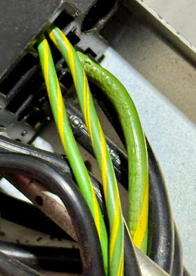
When I opened the connector, I could see that the frame ground wire was taut, not allowing the pin to be pushed far enough in to snap into a locked position. I realized that I had to provide a bit of looseness to that wire if I hoped to repair the connector and make the reader safe for users.
 |
| Inside the housing |
 |
| Problem pin not pushed in far enough |
 |
| Wire too taut (diagonal from lower left) |
After pulling everything apart, I moved the rubber sleeve down on the cable and tightened it in place so that the wires were a bit further into the connector housing. This gave me the needed additional millimeters of wire to push the pin fully into the housing and snap it into position.
 |
| Pin now locked in place |
 |
| Visible slack on wire |
After reassembly the power connector will make full contact on all power pins including the AC frame ground.
CHECKING LAMP CIRCUITS - WITHOUT POWER
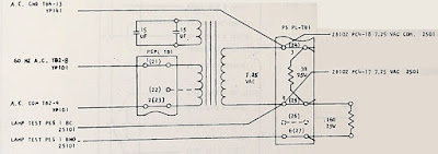
The basic circuit for the indicator lamps has a custom IBM SCR (Silicon Controlled Rectifier) that has the usual three terminals plus a lamp test terminal with an internal decoupling resistor. Power for lighting the lamps is produced inside the IBM 1130 with a very sizable transformer producing 7.25VAC to drive all the lamps on the 1130 and all its attached peripherals.
 |
| Circuits in the 2501 |
One side of the 7.25VAC power supply output is connected to the system's AC ground and to the DC ground terminal strip. This side of the power supply is hooked to the G pin of the IBM SCR. The other side of the power supply is hooked to all the lamps. Each lamp, besides connecting to one side of the 7.25VAC supply, is also connected to the A pin of the SCR.
 |
| Power supply in 1130 |
| Lamp Test switch in 1130 |
The S pin of the SCR is the gate of the device - a positive voltage between S and the G pin will cause the SCR to latch on through one half-cycle of the AC supply until the AC voltage reaches the 0 point at the end of the half cycle. Thus, the lamp is driven by the positive half cycle of the AC supply as long as the signal is positive, but is off when the S input is at or near ground.
The Lamp Test switch on the main 1130 frame connects the 7.25VAC to the T input of all the SCRs in parallel - the side of the AC that is opposite the side connected to the G terminal. This drives the SCR through all the positive half-cycles while the Lamp Test switch remains pressed; the connected lamps light up to allow detection of any burned out bulbs.
I verified that the SCRs had appropriate diode action across all the relevant pins. What remains is to power up the circuits with a bench 7.25VAC supply and check that the bulbs light when the signal input S is high, or when 7.25VAC is applied to the T input, but not otherwise.
Since the connection of one side of the 7.25VAC power supply output to AC and DC ground is done inside the 1130 frame, I will need to wire the bench supply appropriately to all the input pins on the connector. I can then switch on the 7.25VAC manually to the T pins and switch +3VDC to the S pins to complete my testing. This will take place in my next visit to the workshop.


Funny, shouldn’t the ground wire be the longest one by today’s standards so that in an event of a failure of the cable clamp it is the last one to be disconnected.
ReplyDeletebuilt to the standards of the 1950s
Delete