Wednesday, July 4, 2018

Continued work restoring the ASR 33 printer unit

TELETYPE ASR 33 PRINT UNIT RENOVATION

After clearing some sticky residue on the code bars and selector mechanism, I discovered that a spring is missing for bit 4 from the selector, leading to that bit always registering as SPACE or 0. I look throughout the entire printer hoping it was stuck somewhere. Amazingly, I found it jammed behind another spring.

Seems simple, just reattach the spring. The two endpoints are deep in the machine and the loop at the end of the spring is teeny. I first had to detach the carrier return dashpot (shock absorber) just to get better access. Essentially, I need to be in two places at once - pulling from the bottom with one spring hook and pulling from the top with another spring hook - just to get the two ends attached.

I spent a very frustrating 90 minutes trying to set the machine on its side at a stable angle, shine light and get the tools in from both top and bottom simultaneously. Nothing worked, other than dropping the spring many times and having to conduct tedious searches each time.

If I could get my fingers down into the mechanism to make the first attachment, it would seemingly be easier to use a springhook to make the second connection. I removed the connectors to the selector electromagnet, but still couldn't reach.

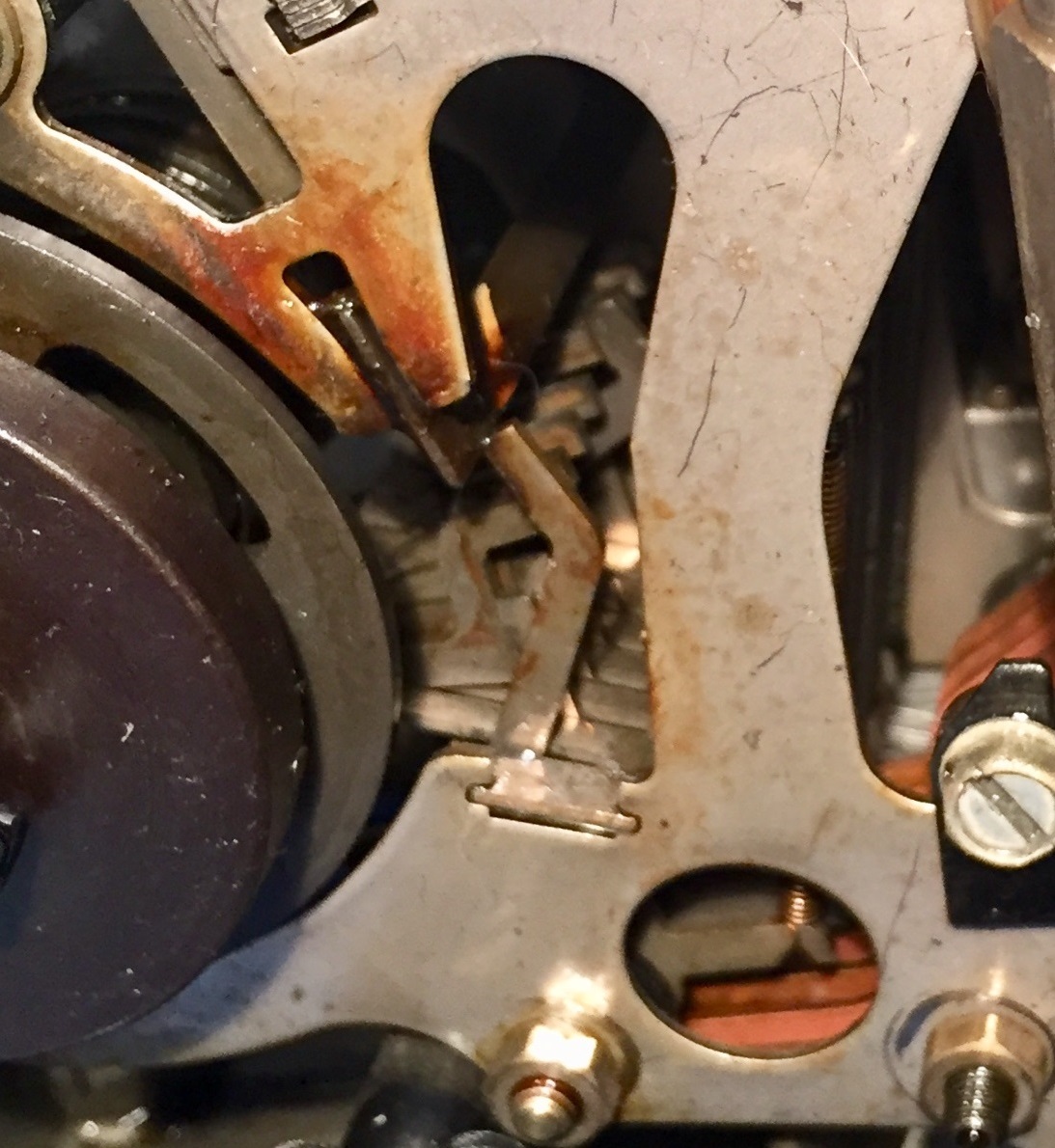
Area where I have to work to reattach the spring
Another hour of failed attempts went by. I really need a pusher type of spring hook, one that fits into the tiny loop at the end of the spring and pushes it away from me and hopefully wrestles it over the tight fit of the tab on the lever arm. I ordered some but won't get them until the weekend.

Ordinary springhook, good for pulling springs
I did come across a tool in the garage, among my selectric typewriter objects, which can be used to grip the far end of a spring and maneuver it over a post. Since this is the first step I want to take, I brought it in and prepared for another stab at attaching the spring.

New tool, with retractable gripping hook
The hook pushed out - it will retract when pressure is removed
I had to use forceps to hold the two electromagnet wires out of the way. I used the new tool and managed to hook one end of the spring over the top post. I couldn't remove the tool or the spring would fall off, so it was important to now push a springhook up from the bottom, grab the other end and stretch the spring out.

Top attachment point is circled
Even this seemingly minor operation took 15 minutes to accomplish, since the spring is angled outward by the new tool making it hard to get the springhook into the other end's loop. Finally, I had it and could release the new tool while holding the spring extended.

The base on which the printer unit rested was slowly rotated while I maintained spring tension, until I could see and begin working on the bottom attachment point. The springhook itself has a relatively large diameter, mostly filling the loop on the spring end and making it impossible to attach. I therefore used a smaller springhook and transferred the spring over from the larger tool.
 
Bottom attachment point is circled
I then maneuvered the end over the lower attachment point! All that was needed now was to carefully detach the springhook and the job was done. Alas, somehow the top attachment came loose as I gently wiggled the springhook on the bottom, causing the spring to 'spring' somewhere and I was back to zero.
After a half hour looking in vain for the spring, which I think is still in the printer mechanism somewhere, I had to put it aside. The spring could also be somewhere in the kitchen nearby, depending on its 'spring' action when it let loose. More wasted time ahead.

I hooked up a power supply to the selector magnet, allowing me to drive the MARK condition as long as I want. The magnet takes 500ma, but I could get it to reliably operate with the current limited to about 300ma. The power switch allows me to control SPACE or MARK as I wish.

The next idea I had was to count the fan vanes on the motor during one entire selector cycle. The protocol transmits 11 bits during that cycle, allowing me to predict how many vanes take me to each of the data bit positions. I can switch the selector magnet off and on at the appropriate times and produce the code bar results I want. 

Monday, July 2, 2018

Printing unit of ASR 33 in fairly good shape after cleaning and lubrication; built RS232 to current loop adapter

WORK ON MODEL 33 PRINTER UNIT

A teletype uses a current loop where a current (20ma or 60ma) is called a MARK and the absence of current is a SPACE condition. When a line is idle, it delivers a steady MARK signal.I held the selector magnet armature in the MARK position and rotated the motor by hand until the printer cleared the prior selected character and all the clutches unlatched. In this condition, the motor spins without any printing action taking place.

If the line is disconnected (e.g. the armature is in the up or SPACE position) then the mechanism detects the space as a start bit and latches the selector clutch to take a cycle decoding what it believes is an incoming character. Since the magnet stays in the SPACE condition, all eight bits of the character are interpreted as 0, which is the "blank" character.

A blank causes the printer to partially print, but the hammer does not actually strike a character. This is the chattering that a teletype will make when the line is disconnected  A blank is different from a "space" character which advances the carrier one column to the right, although both of them cause the partial movement of the hammer called a non-print.

Selector clutch to convert serial input to parallel codebars
If I am careful and slow I can swing the magnet armature at the proper times in a character cycle to set up each intended character. I should see the selector mechanism set the levers and follow the printer either typing a character or performing a function request.

Push levers for each of the incoming bits
Based on the adjustments manual, there is an easier way. Set the magnet to MARK, trip the clutch and rotate so that near the end it has all eight blocking bars raided. Then I would use a springhook to move some levers back to the SPACE state.

Blocking levers above, codebars below at right angles
When typing a character, the selection code causes the type cylinder to rotate and move upwards to place the selected character in line with the ribbon in front of the paper and 180 degrees from the point where the rubber hammer will strike.

If the ASCII encodes a function request such as line feed, the machine establishes a non-print condition to block the hammer from hitting the type cylinder, but also causes a function bar for the requested function to drop into a slot and trigger the function clutch. That would move other bars and levers to cause the printer to feed a line, return the carrier, ring the bell, or other implemented function.
Codebar, function and printing clutches
I worked out the encoding for a few test characters - A, R, bell, new line and carriage return. If the printer unit seems to perform these properly it is a very good sign that it will be quickly restored to full operation. I can do a bit of cleaning and relubrication, put everything back together and begin testing under power.

However, I can see that the selector mechanism sets up the 'blocking arms' correctly for the MARK and SPACE bits of the incoming character, but it should then trigger the code block mechanism to move the code bars left or right depending on their received value. This is not occurring. With the code bars stuck in their off position, every incoming character appears to be a NULL/Blank.

I did a bit of general cleaning, spraying alcohol to rise off dirt near parts that need oil, then applying fresh oil. I can see that the code bar and function clutches work properly, as does the selector clutch. Even the Answer-Back drum clutch works properly, cycling the drum through all the characters that are encoded on it by removing tabs then stopping.

One area that I had to focus on was the distributor - this is a unit that rotates once to serialize input that comes from the keyboard, the Answer-Back drum or the paper tape reader. It keeps turning, even when the Answer-Back drum is at its idle point. I have to figure out what needs to be lubricated and feed so that the distributor clutch also sits at a stop position until needed.

Who Are You drum to encode and send a string back to inquirer
It turns out that the keyboard mechanism will hold the distributor clutch trip arm up, but without the keyboard attached it droops and triggers constant cycles. This will not be a problem when the unit is reassembled - I can see it stop when I manually hold the lever in the proper position.

I tried to set up the first test character - an A - through hand cycling and use of a spring hook. Once I can get the code set up, I would trip the code bar cycle. The goal was to see the right combination on the code bars.

Getting the timing right on the selector cycle is important because the machine is designed to select the next character while the code bar cycle is configuring the print wheel or function rods. Thus, by the end of a cycle I think the character value is locked into position and I can't manipulate it.

I really don't know exactly where I am supposed to pull with the spring hook nor at what time precisely. Until I figure this out I can't fire off character codes and test the remainder of the printer unit.

I was cleaning the punch unit and found a broken bit which initially looked like a segment of a toothed wheel. That worried me because spare parts are difficult to find. After studying the parts manual I realized this was a projection onto which a spring is hooked; the projection had snapped off. This allows setting the tape guide pressure by moving the end of the spring to one of the grooves on the projection.

Broken part I discovered in punch unit
Location where the projection broke off
With the one broken part discovered above, and three external parts that were missing on my unit, I decided to contact the king of teletype spare parts, RTTY Electronics, to see if he has the parts available. I don't have the front plate and the knob to operate the Local/Off/Line switch. I am also missing the knob on the platen.

I never did figure out the technique with the spring hooks during the manual selector cycle, but I was able to toggle the selector magnet armature as I very, very slowly advanced the cycle. It gave me a few printable characters, allowing me to confirm that the hammer does slam the type cylinder into the ribbon and paper.

The last 3-4 tests I would like to accomplish is to trigger function operations instead of typing characters. I want to try out 'space', 'bell', 'line feed' and 'carrier return' as these exercise most of the rest of the printer mechanism. If they work, I think this unit will be ready for power-on testing after reassembly of the entire ASR 33.

What I discovered is that some of the code bars are too sticky to work reliably. I will continue to clean, reoil and exercise them until they work as they should. It is not yet ready to go, but I will keep at it tomorrow. 

QUICK RS232 TO 20MA CURRENT LOOP INTERFACE FOR ASR 33

I whipped up a quick prototype board of a circuit to connect a regulation RS232 (+/- 12V) interface with the two 20ma current loop connections in an ASR 33 teletype. Four transistors, one diode and 9 resistors were soldered to a small board and made ready to wire up as needed to test the ASCII teletypes (model 33).

This will work well with various minicomputers and the Altairduino recreation of an Altair, but can also be used with PC based serial links as long as we insert a voltage translation board to seperate the TTL from the RS232 voltage levels.

For my Altairduino, I had constructed a box which connects over Bluetooth to the Altairduino and presents real RS232 - I used it with one of my HP minicomputer terminals. This will work fine with my teletype and the simple current loop interface. Might have to adapt to the connector I put on the bluetooth box.

Saturday, June 30, 2018

Good progress with model 15/19 teletypes, plus restoration work on IBM 1401 card reader

IBM 1401 SYSTEM CARD READER REPAIR

Our German 1401 system has been down for weeks because its card reader (1402) is unable to read cards without spurious read checks or other errors. It was determined that a set of cams were chipped and broken, causing cards to be fed inaccurately. 

The reader has a hopper of incoming cards, with a set of picker knives at the bottom which have a lip that is less than the thickness of a punched card. These knives push the card toward the entry into the machine, the throat, which has a carefully adjusted slot that is also a bit less than one card thick. This causes one and only one card to enter on each clutched cycle of the machine.

To move the two picker knives at the proper time in a clutch cycle, a pair of offset cams are on a shaft inside the machine. These are constructed of Bakelite, an old, hard and brittle plastic. Two cams are molded together as a unit, but the cams are offset in rotation. One cam will push the knives forward to feed a card and the other cam will push the knives back out of the way.

The plastic cam assembly is chipped, with big enough gouges that it doesn't move the knives at the proper time anymore. The cam assembly is fixed onto the steel shaft with a tapered metal pin. We didn't have a spare cam assembly on hand.

However, the reader mechanism in a 1402 was leveraged into three different machines by IBM. In addition to the 1402, the IBM 360 generation card reader, the 2540, is a somewhat modernized version. The 088 card collator, used in pre-computer accounting machine installations, also uses this mechanism; actually, it has two of the readers, feeding from each side of the machine to common central stackers.

Besides the official collection of the museum, artifacts carefully stored and preserved, there can be units available for public demonstration and education purposes, as long as they are excess to the collection needs of the museum. We are fortunate to have multiple tape drives in this category, for example, from which we can take parts. We also had an 088 collator available for use as parts.

We visited our 088 carcass and examined the two reader mechanisms. The right side feed had some chips on the Bakelite cams, but the left side feed cam assembly was in great shape.

We found that each cam and shaft is pinned differently; each was hand reamed at the factory and sometimes the wide end of the taper was inserted from the back of the cam assembly instead of the front. Nothing was interchangeable without reaming the shaft plus cam assembly.

Mike, one of the newer restoration team members, did the reaming, installed a new tapered pin and cut it to length. He then replaced the shaft in the card reader and made the adjustments for the picker knife timing.

Because we disturbed the multiple CBs (cams with microswitches) on the same shaft, we must re-time all of them to the appropriate range of a rotation of the shaft. The logic in the card reader samples the state of the machine and activates various functions at specific times during the rotation of that clutched shaft. If the times are too far off, the machine detects the error and stops.

Next week we will start doing the timing, adjusting up to a dozen CB microswitches until everything is within specifications. We hope that this will restore the card reader to proper operation.

SECOND USB TO TELETYPE BOX BUILT

I decided to build a second instance of the John Nagle designed USB to teletype box. I had two spare PCBs built, but needed another set of the components to build it up. I placed the order and received almost everything. I soldered in the components tonight and will put it in the case once that arrives; otherwise it is complete.

TELETYPE RESTORATION WORK

We met at Marc's and resumed work on the model 15 systems. I showed Marc what he needed to do for his keyboard to free up the frozen levers on the keyboard serializer/distributor. He began cleaning and addressing issues with his keyboard.

Having cleaned and tested my ASR 33 Call Control Unit (power supplies and interconnection point for cables), I returned it and instead placed the model 33 printer unit in my car for work at home during the week. Once I have this unit working, my aim is to hook it up to my Altairduino (Altair clone) and to produce copies of key software on paper tape and then boot software and interact through the teletype.

My model 15 printer head has so much solidified grease that the main shaft woudn't turn by hand This one will take lots of time to flush out the gunk and free up the mechanisms. I worked on it and have already restored about 20 degrees of rotation to it.

I have pivot levers that drive the function and print mechanisms which are stuck. The clutches on the shaft are also sticky and need lubrication. The big question to me is whether I will need to remove the shaft to fix it or can work on the machine with it in place.

I put the spring back on the model 15 printer - the one that popped off when I was moving the printer when it hooked on my work gloves and pulled loose. It pulls a pivot lever back after the carriage has moved away from the left edge. The lever is connected to a 'dashpot', an air chamber shock absorber which cushions the carriage as it slams to the left edge during a carriage return operation.

My lever and dashpot were frozen in place, but with a bit of lubrication and lots of gentle manipulation, it is working properly and ready to protect during CR operations. My carriage itself, when released, only moves about 15-20 columns over before it sticks. I will be hunting for the cause of the sticking and repairing it.

We focused on the REC30 power supply that came with the model 19 military teletype system. This supply plugs into the 120V mains and produces a regulated 120VDC, supplying up to 600ma of current It is a massive system, much larger than you would expect for a 80W power supply.

Part of the size and weight is a huge autotransformer on the front end which allows use of the supply with a range of power inputs from 25V to 250V and multiple frequencies. It also provides 120VAC output for a motor regardless of the input voltage.

The supply circuitry uses a neon tube to establish a voltage reference, a pair of mercury filled thyratron tubes to produce the DC output, and a pentode tube to control the grids and regulate the output. It also has many chokes in place to block the switching noise of the thyratrons.

The thyratron tubes should have liquid mercury droplets inside which vaporize when the tube is hot, but instead we saw many loose grey flakes inside. That didn't give us confidence in the condition of the tubes but we pressed ahead.

I used my old Heathkit C3 condensor (capacitor) tester, which can check leakage at a range of voltages from 25V up to 450V. Often a capacitor seems fine under low voltage, as checked with a modern capacitor measurement device, but will develop excessive leakage only up at higher voltages. This unit also minimizes the inrush current as you check out these old capacitors.

We found all the capacitors to be good enough to use, acceptably low leakage even up at full voltage. The input to the autotransformer had a reasonable DC resistance, thus we prepared for a power-on test and possible release of magic smoke or worse.

We applied power and saw no signs of failure as the tube filaments heated and the time delay relay heated its bimetallic contacts to allow the thyratrons to vaporize their mercury before power was applied The relay snapped on and the thyratrons developed a lovely blue glow. More importantly, the output was 140VDC and nothing was overheating or smoking.

Initial power on of the supply
We set up a small load to let us measure the ripple and power supply noise as well as adjust the output to its target of 120V. The ripple was only a few hundred millivolts, cleaner than we expected. A quick rotation of the potentiometer and our supply was delivering exactly 120V DC.

I brought my teletype interface box, which we then connected to Marc's other model 15 teletype which appeared to be working properly, based on hand cycling of the machine. I fired up the BaudotRSS program through the John Nagle designed interface and we had the teletype chattering away typing text.

The ribbon is old and dry, but we could read just enough of the text to see that it was getting most of the characters right. We hadn't adjusted the rangefinder, a device that varies the 'sampling' point within each bit cell of the incoming serial stream. We can probably get this typing flawlessly without much more effort.

The Break button worked properly, as registered by the BaudotRSS program, but keypresses were not recognized at all. This might be a problem with oxidized contacts on the Send/Receive/Break switch on the unit. This will be investigated more during our next work session. It was time to head to homes for dinner with our families. 

Monday, June 25, 2018

Worked out ASR33 modification, USB to TTY module working fine

ASR 33 TELETYPE RELAY BOARD UNDERSTOOD AND MODIFICATION DESIGNED

I learned more about that mystery board with the reed relay inside my ASR 33, thanks to some clues from William Degnan. This is a Reader Run Relay, a modification that was made to many ASR 33 units that were hooked to DEC minicomputers. 

The purpose is to advance the paper tape reader under control of the relay, since the DEC interface boards were unbuffered and could easily be overrun if a new character arrived before the last one was retrieved by software. 

If you remember from my last post, I determined that this board would short the Local and Line power  wires together when activated when the relay coil is driven by wires going to pins 5 and 6 of the the DB25 cable. Yes, as I said, that would force the unit online even if it were set to Local mode, but more importantly, it powers the Local wire when in Line mode if the relay activates.

The board had a wire from Local power out to pin 7 of J4, inserted as a modification. I didn't have the paper tape reader side to determine where that power from pin 7 went in the reader, thus I didn't suspect the reason. It appears that these third party boards, of which I found at least two other instantiations besides my own, provide power for the reader motor, under computer control. 

The reed relay in the board is going to respond to RS232 voltage levels, i.e. 12V approximately. If it isn't activated, the tape reader will not function in Line mode, but will run fine when the knob is in Local mode. If not used with a computer driving the relay wires, it won't work properly, but if hooked to a system that suffers from overrun without this feature, it won't work properly WITHOUT the board. 

I don't have a specific plan for a system to connect this to, other than perhaps my HP 1000F minicomputer. Still, I want to preserve full flexibility for the unit, so I won't just strip out the board and undo the modification to the tape reader. 

The solution is to install a jumper that is used or removed by the new owner to enable or disable the reader run board. The jumper shorts the contacts of the reed relay on the board, thus it is always powering the tape reader motor when the machine is in either Local or Line mode. 

This achieves my goal of having an ASR 33 that can be used flexibly, either with a DEC or similar computer that must start/stop the tape reader programmatically, or with a system such as an Altair that properly handles the full speed stream from the tape reader. It makes my ASR 33 valuable to both potential classes of user. 

USB TO TELETYPE INTERFACE TESTING

I plugged in the full size USB CP2102 board I bought and wired the TX line to my scope to watch what comes down the line from Heavy Metal when sending teletype characters. It confirmed the problem I was having - the open to the COM 7 port is not successful.

I suspect the problem is in the mapping of baud rates. The CP2102 is programmed to associate 600 baud requests with 45 baud operation. Therefore one has to open the COM port for 600 baud, 5 bit, 2 stop, no parity in order to communicate. The Heavy Metal program has no option for 600 baud, but does have a 45 baud one. I suspect that it is opening requesting 45, which the CP2101 rejects. There is no choice for 600 baud in Heavy Metal.

I tried Putty, a common terminal emulator program, but it hated 5-N-2 operation and gave up immediately. I will have to sort out this configuration challenge before I move on to the board itself. I tried to whip up a Python program to open the COM port at 600 5-N-2 and loop sending alternating R and Y characters.

After initial errors, I discovered that the lying driver claims it supports 2 stop bits but fails on open unless I set it to 1 or 1.5. With COM 7 configured as 600 5-N-1.5 I opened successfully and verified the proper bits arriving on the TX pin of the UART board.

I think I will begin configuring these as 600 5-M-1 which sends a MARK as the parity bit followed by MARK as the stop bit - in other words, a two cell long stop bit of MARK. This avoids the brain dead Windows behavior.

The problem remains how to get HeavyMetal to open this successfully. I set up the default on the COM 7 port to be 600 5-N-1.5 but again, with no menu choice for 600 baud, I have to select 45 baud from the tool and that makes the open call barf. Next up, how to hack HeavyMetal to add the 600 choice, or perhaps I modify the USB module to use some known rate instead of 600.

I did some searching on the web and found the developer site for HeavyMetal. I run the latest, 3.1.003. He identifies the need to support 600 baud for this USB interface project, but 3.1.004 is in development, not released. S**t.

Now to try to find the other program that is claimed to work properly, BaudotRSS, and see if that will work.To run BaudotRSS I have to configure my Python 2 system with a number of packages before I can run.  Once I am ready to configure all the packages for BaudotRSS, it will give me many more feeds that can be autodirected to the teletype.

It was easier to just hook up the project to my Python program which was repeatedly sending RYRYRYRY at 45 baud. That gave me a fast way of testing the behavior of the project.

Excellent news! The TX lamp on the USB module flashed. The data light on the board flashed. The test points showed 120V developed on the capacitors. My scope showed the proper pattern for the R and Y characters I was sending. Everything appeared happy.

All that is left is to set up a short and measure the current during a MARK condition With no data it should be permanently in the MARK condition. That is the normal idle condition of a teletype line.

I hooked up my VOM to measure the 60ma current that should be delivered, and bridged the output pins of the phone jack. With everything hooked up, I flipped on the switch for the interface. Just about exactly 60ma measured with the output shorted, right on the money.

This is as tested as I can get it without an actual teletype selector magnet and mechanism, e.g. a printer or typing reperforator. Hopefully we can fire this up in a week or two, once we have a working teleype printer from among our two model 15 and one model 19 (actually still a 15).

I am installing it in the project box specified by the designer. I have to measure and cut some holes for the various jacks, switches and LEDs but otherwise it is ready to go.

I did the install for the BaudotRSS program components and tested with this as well. It does seem capable of handling the 45 baud 5-N-2 configuration and may be the program I end up using for our testing and demonstrations. 

Sunday, June 24, 2018

Good progress on the USB to teletype interface debugging, plus restoration work on TTY 15 and ASR33

DEBUGGING USB TO TELETYPE PROJECT

I received two items last night, an alternative CP2102 USB module and a new USB cable. The replacement module has the same signals accessible, but in a different arrangement so that it can't be mounted on the project PCB with headers. Further, it is longer and has a full size USB A connector. However, with several failed boards behind me, I just wanted to have a working USB to UART board with 45 baud support.

I plugged new new board into my PC and it correctly installed and worked. I could adjust its settings using the Silicon Labs Studio development software, converting the 600 baud entry to 45 baud and increasing the current request to the USB host to 400ma to support the project's requirements.

That seemed to point to the original boards as defective, but this morning I tried using my new cable to connect an original board. It worked fine and was altered to 45 baud and 400ma. It seems that I had two bad USB cables with micro connectors - neither had working data lines I guess. The new cable works well. What a stupid reason to have lost a week of head scratching and failed tests.

The new board does turn on /SUSPEND, but after about 20 seconds it is switched off (suspended) until the COM port is opened causing it to spring back to life. This makes sense. Based on that behavior, I tested the original board to see if it turned on /SUSPEND when connected. It did also. 

Given that, I will solder the original USB module back on the project board and resume testing. I will step through the power and waveform tests, watching to see that the device delivers 5V to our main bus and the circuit seems to respond properly. I am NOT seeing the 120V that should be active on the test points while idle, although this requires the first MARK to SPACE transition on TX before it may start charging. Thus, I may have a problem but may not, see below.

Another test that can be done without a teletype is to feed TTY signals from a PC program over the USB cable, watching the LEDs to see that the board is responding appropriately. I am hooked up to Heavy Metal, configured to 45 baud and sending various test streams, but the TX light is not blinking. RX will only blink if I activate the keyboard, which I am not doing since it is disconnected.

It is likely that I have the configurations wrong in Heavy Metal and am not actually sending data over the USB link. It opens the port properly, as the /SUSPEND goes high and allows me power to my interface. I don't, however, see any SPACE values coming down the line. I need to debug this first, since I need to send characters before the charger circuit will develop the 120V reservoir.

The last test before hooking up a real teletype is to short the output and measure the current being delivered - this should be 60ma. That indicates that the proper voltages and currents are being developed. I might be able to do this during the steady MARK condition even with no data coming over the USB link. A project for tomorrow. 

CHECKING OUT POWER SUPPLY FOR ASR 33 TELETYPE

I brought home the power supplies (the Call Control Unit as named by Teletype) to check it out and restore it if necessary. First up was to use my old Heathkit Condensor Checker, which does leakage tests at varying voltages up to the limit of each capacitor. There were three big electrolytics to test. One of them is marginal and I will replace it later, but all are good enough to run with for now.

First power on tested the main power switch, which has three positions - Local, Off, Line. When in the Line position, a relay loudly activates, as it should, but not in Local mode. I then tried to note all the connector points where I should be measuring power - various AC and DC voltages are developed in this unit.

The documentation is far from clear. No way to easily spot where various voltages or signals are placed on connectors. Finally I came to understand what "R 5C4" and "3A5 or 4A6" meant. The first number is the relative schematic page, titled as "Sheet 3" for example. The remaining characters are the row and column on the page where the wire occurs. 

I found an exceptionally obscure card, looking like it was not made by Teletype, wired into my unit. It takes two wires from the DB-25 computer connector, pins 5 and 6 which are green and brown, to the coil of a reed relay. Thus, some power from those wires will energize the reed relay. 

The contacts of the relay bridge the L1 and L2 poles on the main LOCAL/OFF/LINE switch, thus making the unit both online and local simultaneously. I believe it forces the teletype to be online, even if the rotary knob is set to Local. The modification also provides power while in Local mode to pin 7 of J4 - purpose not yet known but will check when I have the rest of the teletype on hand. 

The only power generated in the Call Control Unit and its modules is:

  • 120V to the motors when in Local or Line mode
  • DC power, 34V to drive the selector magnet for the printer, based on line or keyboard current
  • DC power to drive the current loop line from the automatic tape reader (120V or higher)
  • DC power to drive the internal current loop in local mode (67V) since it is half wave rectified

I verified all but the automatic tape reader supply, using my VOM, but that didn't work for the ASR power since it is driven through a plug on the reader cable that is not at my house at this time. However, I checked all the components with my VOM and diode tester, until I was satisfied that it should work properly when connected. 

At this point, I have finished the checkout and restoration of this second portion of the teletype, the Call Control Unit. The remaining units to test are the tape reader, tape punch and printer units, which will wait until Friday when we get together for the next burst of Teletype restoration.

TELETYPE MODEL 15 RESTORATION WORK

We lined up all the model 15 and model 19 teletype machines and began with a good cleaning to remove dirt and lubricants. This consisted of mainly scrubbing with Simple Green but some Alcohol and other cleaners were needed for a few special places.

My Model 15 and Marc's Model 19 have similar motor baseplates and we worked on them first. They have two power plugs and two telephone exchange style plugs. One power plug consists of three prongs in a triangular arrangement. It is used to supply 120V DC for the current loop signal lines. The other is a four prong outlet, three that are oriented in the same direction and the fourth rotated 90 degrees, used for 120V AC to run the motor.

We studied the schematics and wiring to determine that the four prong plug is arranged with ground on the one plug that is perpendicular to the others. The three that share an orientation are arranged at the other four corners of a Rhombus shape. The corner opposite the ground pin is the neutral line. The two other pins are both for the hot leg of single phase 120VAC.

There is a difference inside the teletype base. One of the hot pins runs through the ON/OFF switch and motor control relays, while the other is routed directly to the motor. Thus we call them the switched and unswitched lines; we plan to only use the switched hot wire.

The Model 19 desk had several of the four prong receptacles into which this plug will fit. Marc took one and wired it into a handybox to give us a proper outlet to plug in our teletypes. Before we ran them, however, we re-oiled the bearings and worked out stale lubricants. Finally, we could plug in both baseplates, flip on the power switch and watch the motor spin happily away.

I moved on to work on my keyboard mechanism. This is built with five rods (one per bit of the 5 bit teleprinter or Baudot code). The keys on the keyboard each have a rod, oriented perpendicularly to the five encoding rods, with the key rod having notches that will force each of the encoding rods left or right, depending on whether that bit of the character could should be a MARK or a SPACE.

My keys worked well and those encoding rods did slide left or right reliably to encode the character. What did not work was the distributor that should serialize those rods into a sequence of a start bit, the five data bits in order, and a longer stop bit. To do this, a clutch latch has to be triggered by a sixth bar, similar to the fire encoding rods but always depressed - thus called a universal lever.

When the clutch is released, the distributor should rotate 360 degrees under motor power and latch again, waiting for the next keypress. Multiple cams on the axle operate switch contacts at the appropriate point during the rotation. First, breaking the circuit to produce the SPACE value of a start bit. Then, either making or breaking the circuit based on whether each bit in turn should be MARK or SPACE, then generating a MARK signal for the remainder of the rotation as the stop bit.

The cams push on levers that can be allowed to swing out to make contact or blocked, depending on the left or right position of each encoding rod. Those levers pivot on a shaft, or should have, but they were corroded into place.

I had to use 3 in 1 oil and about an hour of time patiently wiggling and rocking each of the six levers (five data bits plus the start/stop contact) until they moved freely. When I was done, I had also lubricated the shaft bearings and had the clutch release working well with the universal lever. Now, I could push any key and trigger a rotation with the right sequence of on and off current flow to encode that character. My keyboard was restored and ready to use.

We were near the end of the workday, permitting just enough time to assess the other parts and prioritize next week's work. Marc's model 15 (19) keyboard had the same frozen levers that mine had, so this will need an hour or so of work to free up. His printer unit main shaft rotates, which is a good sign. My model 15 printer unit has a main shaft that won't turn at all - frozen lubrication strikes again. 

Thursday, June 21, 2018

Mainly debugging the CP2102 breakout boards, while the project itself seems to be functional

USB TO TELETYPE INTERFACE DEBUGGING

I received my replacement USB board (CP2102 board specified by the designer of the interface), plugged it into my two PC and one Mac systems, but it continues to be rejected as malfunctioning. I have wasted two hours doing shutdowns with battery removal for five minutes, restarts and other actions to try to get the board to talk to a PC of any type.

I hauled out my Surface Pro, yet another windows PC, and got the same error message. These little boards are s***t. I did order a brand new microUSB cable, just on the one in a million chance that my cables themselves are bad. We shall see.

Meanwhile, I need a plan B. The maker of the chip that is on the USB board has its own evaluation kits, which might get me some official support. Also, they are more likely to work than these low cost boards from China. The kit does not have the DTR and DSR pins connected, while the China board brings these out to the headers.

The interface design bridges DTR and DSR, but if the module is to work while loose, where they are not connected, then this seems superfluous. This is important because the evaluation kit boards from SiLabs do not bring out DTR or DSR to any accessible point. If I don't need them, then this board could be a suitable replacement.

Alas, the one feature that is required to run at 45 baud is called baud rate aliasing, and it is not supported by the newer CP2102N chip and the evaluation board. I would have to ensure I got a board with the original CP2102 chip to have this work. Before anyone suggests the rock solid FTDI based boards, they can't be configured below 214 baud.

There is such a board, but it is not the same form factor and connectors as the one from China. It will cost me about $35 plus shipping for this board and I might not be able to fit this into the case for the interface project since it depended on the small micro-USB board rather than this larger one.

I will wait for my new USB cable and continue to bash away at all the machines until I get one to accept the module. This is extremely frustrating when a single component isn't working and blocks progress on a larger, complex project that uses it.

I did a return of the module, second in a row that didn't work. I still have the first one, the unit where I had removed the angle pins and connected it to my board. I will use that as a final check with the new cable coming tomorrow.

Once the cable arrives and doesn't fix the problem, I will pull the trigger on the more expensive SiLabs evaluation kit board. I will then have to work out the technicalities of mounting the board since it does not match the holes established in my main PCB.

If my cable fixes it, I will stick the board back on my main PCB and test, of course. One way or another, I need a usable serial port operating at 45 baud to communicate with the project. I supposed I could go old-school and wire up a voltage translator and DB9 to use an actual serial port on an old PC, although there is no guarantee that the PC UART can operate at 45 baud so this is not a good alternative.

I decided to test my main board using a current limited power supply and some jumpers to trigger various conditions. The first is /SUSPEND, which should cause my Power LED to glow brightly. The second is TX, which should flash the Data LED. I can make various voltage and current measurements to prove out the rest of the board.

Discovered several things. First, the signals from the USB daughter card to the main PCB will be detected as high unless I ground them. They don't need 3.3V to activate. With /SUSPEND floating, it is high and my board powered up

Second, I discovered that the damned documentation for the project is wrong. The PCB has a triple LED module, three vertically arranged green lamps, claimed to signal Power, Motor and Data from top to bottom. Wrong! In fact, from top to bottom they signal Data, Motor and Power.

Grounding various pins on the PCB that would connect to the missing USB board, I confirmed that Power lights properly as soon as I flip on the on/off power switch. Now, for the voltage checkouts. Test points were provided on the board to test out its behavior. The main bus voltage should be 5V if the switch is on and the /SUSPEND line is high. I checked, pulling /SUSPEND to ground which validated proper operation. 5V when it should be, matching the Power LED.

When I ground RTS/CTS lines, the Motor LED lights.  Another deviation from the documentation which claims that Motor Control goes on when RTS/CTS is high, but in fact it only goes on when they are low. This is fairly useless as developed. I will think about adding an inverter between the USB board and the CTS/RTS lines, ensuring that this works as intended.

When I hook the TX incoming bit line to 3.3V, the Data LED turns on. Leaving it floating or at ground turns off the LED. However, while working on the board I noticed that my Power LED would blink off about once a second - the power draw went to zero coincident with those excursions. It appears that the internal power regulator is detecting overcurrent from the main bus and protecting itself in that periodic pattern.

The big question is why I am exceeding the current that this design should use. Time to check continuity and parts to look for possible issues. This may simply be due to an unconnected load and steady MARK or SPACE for relatively long durations.

I found a CP2102 board which has a full size (A) USB connector and all the requisite signals, although not matching the pins or outline of the twice defective board. I should have it on Saturday and can see if this can talk to Windows or OS X. If it works, then I can address the mounting challenges and use discrete wire to connect each signal to the main PCB board header pins. 

Tuesday, June 19, 2018

Cleaning up board, identifying bad USB module

DEBUGGING THE USB TO TELETYPE INTERFACE

To rule out a problem with my USB daughtercard I ordered another and expect to have it by Thursday morning. I will make sure that the software link to the PC works before I make any changes or insert it on my main board, thus ensuring that Windows, the board and my reconfiguration of the device to support 45 baud operation are all good.

I was going over my main board checking components before doing signal continuity tests when I discovered two diodes that were not connected in spite of the solder blobs left by the reflow. I decided to resolder all the points manually, which brought those components back to proper readings.

The board works differently now, as the small power LED does not light any more when I plug in the device. Checking other components showed me that quite a few of the capacitors were shorted underneath. I suspect that I have a few suspect soldering connections and will therefore remove each such component with my rework tool and hand solder them back after cleaning up any solder bridges on the board. This is tedious work, but important.

The green light is back on, but the USB board is still stuck with the red RX led illuminated and it won't respond to the PC in order to load drivers. By Thursday I will have a definitive answer about this board, but the first step is to remove it from the main PCB and see if it will chat by itself. I need to remove it anyway in order to install the new USB card.

Looking over the schematic, I see that the 5V from the USB link is only delivered to the main board when the power switch is on and the USB driver board has indicated it is out of suspend mode. As the board won't syn up with a PC, it is suspended. The PCB has a current limiting chip that has an enable pin hooked to the USB module, only allowing the 5V power to flow to the rest of the circuit when the USB module is not suspended.

This means I should not have the green power LED illuminated, especially if the main power switch is turned off. But it glows! I suspected that the RX lamp is lit on the USB module and is driving some path that reaches our power LED. I then checked the schematic and tested for continuity and shorts in the relevant areas.

Turns out the RX side of the USB daughter card is connected to a 1K resistor to ground and through a pushbutton to some other circuitry. Opening the pushbutton does not extinguish the power LED, nor is there a path from the RX signal over to the power LED at all. That means I have some other sneak circuit that delivers some voltage to the central power point of the board (and thus to the power LED), but not the 5V supply.

It has to be one of the other connected lines, TX, RTS/CTS,  or /SUSPEND. If TX were delivering power it would also light up the Data LED, so it is probably not the problem. Still, I checked for continuity and shorts for all the lines that might deliver power to the central bus (other than the intended path of VCC through the current limiter and on/off switch).

There is a path from the TX line to the input of an inverter, which in turn drives an enable pin on the charging control chip. If the inverter is blown out somehow it could provide a sneak path, from the input to the VCC pin, but I see infinite resistance with my VOM.

In any case I did a couple of experiments removing parts temporarily. With the 1K resistor lifted from the RX circuit and the Break button pushed, the RX LED on the USB board was extinguished. It came on with the Break button released, just as it goes on when the 1K resistor is reinserted. The voltage of this line is about 0.9V, which is what is present on the main bus and driving the green Power LED dimly.

I removed the inverter chip that might have leaked, even though the TX line is at 0V. Of course, the dim Power LED remained on. The measured voltage on the main bus is 0.9, exactly the same as the RX line. If the TX line were to rise to 1V or higher, the Data LED would illuminate, but it did not.

The path from RTS/CTS runs to the motor control relay chip pin but the other side of the input line is isolated by the on/off switch. I don't think this is the problem either.

The RX line passing through the Break pushbutton goes to the solid state relay chip (CPC1510G) U6 that will close a circuit to connect the RX pin to the main bus (+5V). This is controlled by the flow of 24V from the buck-boost chip, through the keyboard jack and a resistor. If there is enough flow, it will trigger the relay and connect RX to the main bus. This must be happening.

The 24 volts from the buck-boost chip shouldn't be on, since the main bus is off when we first plug in. The buck-boost takes the main bus voltage as input to produce the 24V output. There are two possibilities here. First, the relay chip could be bad, although my VOM shows it open in the idle state. Second, I might have a undetected short to some other line that produces current for the relay. Third, the buck-boost might be working anyway.

To eliminate the third chance, I inserted a dummy plug into the keyboard jack, opening the circuit. This should ensure that the relay doesn't close and pass RX at 0.9V to the main bus. Even with the removal of the relay U6 I didn't drop the main bus voltage, so if I don't have a hidden short then this isn't the cause.

I do have 3.3V coming from the RTS/CTS pins of the USB board, which would fire the motor control solid state relay U7 if the other side were connected through the on/off switch to the chips VCC. The VCC line goes through a 1.8V Zener diode and resistor, through the LED inside the photorelay and back to the RTS/CTS line..

That should cause the middle (Motor) LED to light in addition to the power one, since they would have the same main bus voltate in each case. It is not, which makes me suspect that the motor relay is inverted, it 'fires' when RTS/CTS is at ground level, turning on the motor control relay and LED, then when CTS/RTS goes high to 3.3V, it switches off. This doesn't make sense compared to the description of the circuit operation.

As long as the USB chip is not talking nice to PCs and not raising the /SUSPEND signal, the rest of the board won't be working. At this point, with my new USB module arriving tomorrow, I decided to remove the existing module to see if it talks to the PC when out of circuit.

To heap a bit of extra annoyance on the situation, Windows has the delightful practice of shutting down the USB ports for a device after a few Device Malfunctioned (error 43) situations, requiring a power down and reboot to clear it. After I completed this unnecessary time sucking task, I plugged in the CP2102 board by itself

Still malfunctioning and not recognized by Windows. Good thing I have the replacement USB board on its way. Thia was what I suspected but this proves the case. I need a functional USB module to make the main board work.