Monday, January 29, 2024

Replacement current column pointer installed

1053 COVER REQUIRES SPECIAL POINTERS DUE TO DEPTH OF ENCLOSURE

The cover of the Console Printer (1053) has the Selectric mechanism against the rear edge, leaving room in the front for the Console Entry Switches and other controls without interfering the the carrier and other typewriter parts. The extra room is only about two inches of depth, sufficient for the toggle switches and other additions. 

In an ordinary Selectric, such as office machines, the cover sits just in front of the typewriter mechanism so that the pointers for current position and margins are less than one inch long and still stick out of the front of the cover. The corresponding parts for the 1053 must extend out the extra two inches, thus the margin release levers and the column pointer are unique to this model.

The front panel of the 1053 has a plexiglass window running the width of the print line but a fraction of an inch high. There are column numbers and tick marks on this panel, allowing the operator to consistently set margins and space the carrier to a desired column of the print line. 

The tips of the margin levers and current column pointer are roughly triangular as they sit just behind the window, with the tip pointing at the tick mark where they are set. The margin indicators are blue and the current column pointer tip is metallic silver. The levers and pointer extend out from the margin rack and carrier and have the tip just behind the window at the appropriate height so they can be seen. 

SHEET METAL REPLACEMENT COBBLED TOGETHER

I measured the pointer from my working 1053 and fashioned a substitute from some sheet aluminum using tin snips and a drill, giving me a metal tip that would be visible in the window at the proper point. I mounted this and tweaked it until it was suitable. 

The pointer looks a bit rough up close, but all that is seen by an operator or museum visitor is the metal tip through the window. Just as the repair of the broken right margin lever is not visible except when opening covers or working on the machine, this pointer is similarly hidden. 


Thursday, January 25, 2024

Proper donor typewriter identified and bought - should arrive in a week or so

I found a Selectric 1 (original) 13" model on eBay. The seller included a photo of the broken rotate metal tape which occurred as he tried to lubricate the machine. In that picture I can see the ends of the paper feed mechanism (barely, with adjustment of exposure and contrast) and these look to be definitive for the tie-rod style paper feed mechanism. 

The shipping definitely adds to the cost, almost the same cost as the typewriter itself due to weight and size, but I didn't see any local Selectric 1 13" models that I could drive and pick up in any of the online marketplaces I tried. 


Wednesday, January 24, 2024

Installing the missing paper feed parts and levers - part 2

DONOR MACHINE PROCURED - FIRST TRY

I found a 13" paper width machine that had the tie rod paper feed mechanism. It was nearby, only $80 and while listed as a parts machine it appeared to only be suffering from solidified lubricants. I bought it to remove the parts that were missing from the 1053. 

I thought I had checked that it was a tie-rod style, but when I removed the cover, it had the useless A-frame mechanism. I tore it apart to harvest parts that I might need for other 1053 repairs. Time to look again to find the right kind of machine. 

The paper feed mechanism is hidden inside the cover of the typewriter, but some could be seen if the platen is removed, the chrome deflector has to be taken up as well and then I need a decently lit focused picture in order to verify the type of paper feed installed. Most listings for used Selectric typewriters consist of blurry or exterior only pictures. It can be hard to even see the paper centering scale that proves it is a 13" machine rather than an 11" or 8 1/2" model. 

Process of stripping the new donor for parts


Tuesday, January 23, 2024

Installing the missing paper feed parts and levers - part 1

MORE ABOUT MISSING PARTS ON THE 1053

Here are pictures of the machine with its parts missing. 

left side

middle

right side

missing lever parts inside

missing lever parts outside

Next I show pictures of my own 1053 with the parts in place for comparison.


DONOR MACHINE POSSIBILITIES

The 1053 is a 13" machine - the size of the printable area from leftmost column to rightmost column. Further, it uses the tie-rod style paper feed mechanism. Very fortunately, not only did the 1053 not change this area at all from the office products typewriter versions, but IBM did not change the tie-rod mechanism at all between Selectric, Selectric II and Selectric III models. 

Pretty much any 13" machine with tie-rod feed is a suitable donor. This gives the largest possible pool of used machines that could be exploited to donate the missing parts.  I am confident I can find a machine within easy driving distance that I can verify as a tie-rod model before buying. I am feeling much more optimistic about the full restoration of this 1053. 

ANOTHER MISSING PART DETECTED - POSITION POINTER

The 1053 has a long metal rod attached to the front of the carrier whose tip is visible in the window of the printer front panel. It shows the current column where the carrier is sitting. On regular typewriters this is a short red pointer. 

Pointer on my good 1053 

missing pointer on 1053 being restored

I believe I can fashion a replacement from sheet metal since that is the material used on the original IBM part. Basically a matter of measuring, cutting out the shape, drilling two holes and then putting a few bends into it. It will be good as long as the tip is the right distance forward of the carrier, the proper height to be in line with the two margin lever tips, and the correct distance to the left of the mounting point to properly identify the carrier's current column position. 


Monday, January 22, 2024

Investigation into replacement of missing feed roller parts on 1053

MISSING PARTS ON 1053

The console printer, a 1053 I/O Selectric, was missing the parts that fit under the platen and press the paper against the surface of the platen. There were quite a few parts missing as you can see from the diagram below. I drew over the few parts that were still in place using a grey aerosol brush effect.

Greyed out the few parts that are not missing

These are essentially pivoting levers that are spring loaded to swing up against the underside of the platen. Shafts with rubber feed rollers are inserted into these parts - the shafts/rollers were not missing nor was the platen. A Selectric has front and rear feed roller shafts, which fit into a cradle that pivots on the larger lever that in turn pivots on a heavy rod. 


These must be able to move out of the way when releasing paper thus the mechanism has additional pivots and springs compared to a design that might have a fixed position under a platen. The paper release lever on the side of the typewriter connects to these parts. 

CHECKING WITH OWNING MUSEUM

I asked the museum which owns the 1130 to look for the missing parts as it is possible they are on a shelf near where the machine was being worked on before it was transported to me. Hopefully they will find those parts, still assembled into groups I imagine, and ship them to me. 

ALTERNATIVE DONOR MACHINE

The donor office Selectric machine I have uses a very different and less rugged feed system that does not appear compatible at all with the 1053. I would have to get lucky finding a machine from which I could harvest the needed parts. The donor is a 11" machine while the 1053 is a 13" model. That might result in the use of the different design even on office machines, but I needed to do some research.

What I discovered was that the paper feed mechanisms are divided into two types - A-frame and tie-rod. The donor typewriter had an A-frame but the 1053 uses the tie-rod feeds. The parts look like they will be much more widely available as long as I find machines with tie-rod paper feed mechanisms. 

The original Selectric, retroactively called Selectric 1 by collectors, came in three widths, 8 1/2", 11" and 13" although some very specialized office machines for banks had much wider carriages. The 1053 is a 13" model. Apparently all I need is to find a 13" tie-rod machine, probably a Selectric 1. 

I can figure out whether a typewriter is a 13" model by looking at the inch markings on the paper entry guide. What I can't tell from most of the pictures is what kind of paper feed mechanism is under the cover. I might have to drive to several and look inside before buying. 


Repair of the right margin lever and reattachment to the 1053 - part 2

TESTED EPOXY BOND OF BRACKET TO STRENGTHEN THE LEVER

The bond between the metal bracket and the plastic lever was strong enough to work. It was not the best cosmetic fix because of the bracket, but that part of the machine is only visible when a user is looking down in the console printer adjusting the margins, so not very often. 

INSTALLED LEVER ON THE 1053

I put it back on the machine and checked that it performed as expected. 


Saturday, January 20, 2024

Substitute ribbon color control tape installed and adjusted on 1053; discovered missing parts

DUAL RIBBON COLOR FEATURE

An optional feature that IBM developed for the Selectric typewriters was the ability to print in two colors, selectable at any time. This made use of ribbon cartridges whose nylon fabric ribbon was loaded with both red and black ink. The colors were divided across the length of the ribbon, so that the height of the ribbon when it was lifted for typing would determine which ink was in front of the character on the typeball. Black is on the top and red on the bottom half of the ribbon. 

This allows a programmer to make use of red ink to highlight specific conditions which otherwise might be missed in a sea of black typed output. The program can command the 1053 to shift to red or shift to black at the appropriate times. It is even possible to alternate colors column by column. 

The carrier of the typewriter has a ribbon lift mechanism on all Selectric based machines. The ribbon is down below the current line being typed in order to give the typist good visibility of what they have already typed and of printing on paper forms. When a character is being typed, the carrier pops the ribbon up in front of the paper so that the ball strikes through it. This lift mechanism could be disabled for special purposes such as typing a stencil where ink was not desired. 

The modification changes the lift mechanism to support three target positions for the ribbon - down (stencil), up in the bottom (red) half of the ribbon, and up in the top (black) half of the ribbon. A tape increases its tension to pull on a lever inside the carrier to select the red half, otherwise the lift moves to the black half due to a spring inside the carrier.  

This tape runs left and right over pulleys, much as is done with the metal tilt and rotate tapes or the carrier motion cord. Thus the cord or tape has a constant tension at all columns from left to rightmost on the typewriter. By pivoting one of the side pulleys, the tape or cord is given a different amount of tension which is transferred to the mechanisms inside the carrier. 


A pair of solenoids at the left bottom side of the 1053 move pulleys up or down, which add or release tension on the tape that controls the ribbon lift. The tape for the ribbon color routing:

  • attached to the right edge of the carrier
  • runs from the right side of the carrier to the right edge pulley
  • reverses direction at that pulley
  • runs leftward all the way across the front of the typewriter to the left edge
  • the left edge has  a pair of pulleys for the tape
  • it changes direction downward on the left side
  • loops over a pulley on the solenoids
  • returns upward and changes direction gain on the other of the pair of pulleys at the left
  • it continues rightward to the carrier 
  • it turns around a small pulley in the front of the carrier
  • that routes the tape inward to its attachment to the ribbon lift mechanism. 
Armature with pulley down adds tension to select Red ink

UNOBTAINIUM PLASTIC TAPE MISSING FROM THIS 1053

This 1130 system had no ribbon tape and there are no supplies anywhere of replacement tapes The dual color feature is found on very few machines, thus I can't find donor typewriters from which a tape can be retrieved. I had tried several materials to construct a replacement that would work properly, allowing the programs to type in both black and red ink as desired. 

FASHIONED REPLACEMENT WITH LACING CORD STRING

Lacing cord is a heavily waxed string that is used to tie bundles of wires together, with knots periodically along the wire lengths that don't unravel easily. It did not stretch under the kinds of tension found in the ribbon lift mechanism and seems to be fairly durable. 

INSTALLING HOOKS ON END OF CORD

The lever inside the carrier has a small hole in it and on the IBM plastic tape there is a triangular shaped wire end that hooks through the hole. A similar wire end on the other end of the tape allows it to be fasted to the right end of the carrier. That can simply be knotted in place since it is readily accessible on the outside of the carrier. 

I found some springy wire material in the donor Selectric and used it to fashion a replacement hook. When fastened on the end of the replacement tape, they can be connected to the ribbon lift mechanism inside the carrier. 


I tied the cord to the clip and worked the clip onto the mechanism inside the carrier. It took a bit of work as my clip was larger than the IBM original equipment, but it fit nicely.

In the midst of attaching clip

ADJUSTING THE CORD FOR PROPER OPERATION

The right side pulley for the ribbon tape has an adjustable screw to move it left or right, allowing the tape to be set to a tension that selects one color or the other properly as the solenoids work. I attached the substitute tape (cord) connected to the clip inside the carrier, routed it around the pulleys and attached it to the fixed point on the right of the carrier. I then adjusted the right side pulley such that the ribbon lifts to the desired position with the solenoids shifted to each of their two states. 

The solenoids were out of position such that they wouldn't work properly. Much like the pair of solenoids used for the shift mechanism, the two work together to lock into one of two states, in this case red ink or black ink state. When the armature connected to the pulley (see below picture) is pulled downward by the solenoid magnet you can see there, the small vertical armature on the left would be pulled under the pulley's armature to lock it in the down (red) position. 

Activating the other solenoid whose vertical armature is visible on the left of the picture will release the pulley's armature which pops back up. This relieves tension on the cord and shifts the ribbon mechanism to the black ink side. However, when I push down on the pulley's armature the vertical black armature cannot slide underneath to lock the machine into the red mode. 


I loosened the mounting screws and moved the solenoid in the picture until the pair worked properly. When the red solenoid is energized the pulley's armature pulls down and the vertical black armature locks it in place. When the black solenoid (is not visible in the picture) energizes, it releases the pulley's armature and therefore the pulley moves up into the black position. 


The movie clip above shows how the setting of the pulley to its down or up positions results in the lever inside the carrier moving between its two extreme positions. This should complete the repair of the color selection mechanism. I began setting up my test rig so that I could print characters in both colors to verify that no other ribbon lift adjustment needs to be corrected. 

To print on paper, I had to put on the rollers, guide and platen in order to feed a piece of paper into the machine. I have a couple of dual color ribbons from my 1130 system and would put one on the machine to test the color printing; the machine was delivered with a solid black ribbon but the dual color ribbons are available for purchase. 

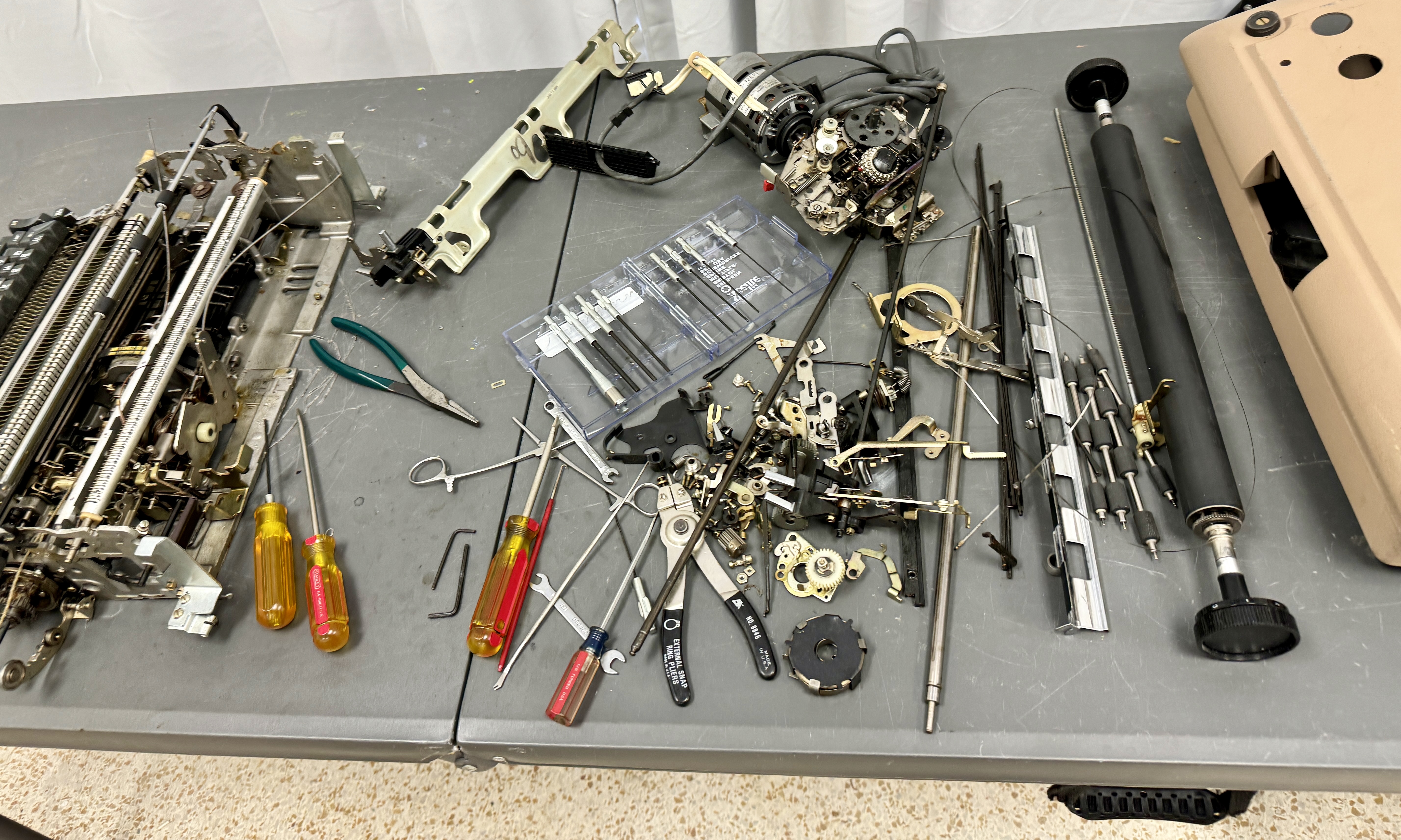
I brought everything over and when I began to install the four rubber feed shafts it became obvious that the part of the machine into which the shafts are placed was missing. When I received the 1130 system it had the rubber feed shafts and chrome paper guide in the spare parts box. I never had a reason to install them until the typewriter was working and I frankly didn't pay attention to the missing parts until now. 

I have a picture of the machine with its missing parts just below. There are levers, shafts, springs and other parts missing, probably all connected together on the Feed Roll Actuating Shaft sitting somewhere. Hopefully we can locate this and get it to me in order to have a usable console printer. x

SSM 1053 with missing feed roller parts

Have only feed rolls, deflector and platen, all else missing

Another view of the missing parts

My 1053 has the parts in place, for comparison

The donor Selectric uses a different and simpler feed roller assembly, plus it is a shorter page width than the 1053, so it is not a simple matter of swapping in the parts from the donor machine. Fingers crossed we can locate the missing parts at SSM and get them back on the 1053. If not I will have to see what we can do to find replacements. 

CONTINUED REPAIRING THE RIGHT MARGIN LEVER

I made use of a bracket from the donor Selectric and some epoxy to apply the bracing across the line where the part had snapped apart. I need to give this a good 24 hours to harden to maximum strength, after which I can test whether it seems solid enough. If so, I can install it on the 1053 and complete that item on the restoration checklist. 

Lever as the epoxy sets


Friday, January 19, 2024

Repair of the right margin lever and reattachment to the 1053 - part 1

SPECIAL MARGIN LEVER DIFFERENT FROM STANDARD SELECTRIC TYPEWRITERS

The 1053 Console on the IBM 1130 has a print only I/O Selectric with a front panel that features some pushbuttons and sixteen toggle switches. Because of the room necessary for the toggle switches, the front panel is further from the typewriter mechanism that is the cover of an office Selectric typewriter.

Thus, the shorter margin levers on an office typewriter stick through a slot on the cover and are moved side to side by the typist without opening any top covers. On the 1053, however, there is a plastic window through which the tips of the longer margin levers can be seen. The operator must open the top cover and reach down to move the margin levers. 

Left margin lever tip visible above red arrow

When you compare a typewriter margin lever to the 1053 lever, the typewriter part is wider and shorter than the 1053 part. This makes it impossible to substitute an office typewriter lever. If it had not been wider, it could have been mounted inside and moved by the operator but the window on the front panel would not show the margin position because the lever was too far back. 

GLUING TOGETHER THE BROKEN PIECES OF THE MARGIN LEVER

I did a test glue-up of the two levers of the donor Selectric - they bonded well. However, when I tried the same glue on the 1053 levers, it didn't soften or melt the plastic surface at all. Definitely a different type of plastic. 

The break is in a narrow section thus there is not a large surface area for bonding. I used some Cyanoacrylate ('super glue') which has provided a pretty weak connection but the two parts are together at least. This is not strong enough to use as it is.

Lever with first bonding completed

My plan is to add a bit of material to span the flat areas over the repair, using epoxy to hold everything together. Hopefully this will result in a strong enough part to re-attach to the printer. 


Thursday, January 18, 2024

Fixing carrier return and shift operations

CARRIER RETURN FAILURE TO LATCH AND CONTINUE MOVING

The carrier return function is a complicated mechanism with a sequence of operations that are necessary for a return to work correctly. It is spread across several areas of the machine as well. The sequence that must occur is:
  1. Trigger is released for the return operational lever, by solenoid or pushbutton
  2. The right hand operational clutch takes on 360 degree cycle
  3. A cam on the operational clutch moves a bail down and up during the cycle
  4. A lever for carrier return is pushed under the bottom lip of the bail 
  5. The clutch restores the operational lever at the end of the cycle
  6. The lever pulled down and released by the bail turns an activating linkage
  7. The early movement of the linkage pulls the rod to arm the margin release bar
  8. The arming of the bar also latches the activating linkage 
  9. The latched linkage continues to stay down after the operational clutch cycle ends
  10. The latched linkage holds the escapement and backspace pawls out of their racks
  11. The latched linkage also forces the nylon shoe onto a spring to power the return
  12. The powered return winds up escapement cord on the return drum
  13. The powered return winds the main spring, adding energy for future space and tab
  14. The winding of the escapement cord pulls the carrier to the left
  15. When the carrier strikes the left margin lever, it pushes the margin release bar rightward
  16. The carrier is decelerated by a air cylinder that cushions the carrier to a stop
  17. The movement of the margin release bar pulls a rod to disconnect the activating latch
  18. The nylon shoe comes off the spring and the leftward movement stops
  19. The escapement and backspace pawls re-enter the rack to hold the carrier at this column

Green line is Carrier Return Unlatching pushroid


Upper pushrod that arms the margin rack

Early on in this sequence, when the activating linkage starts moving, it should have armed the margin release bar. This did not happen. Without the bar being armed, the latch mechanism is pulled out of the way so that the linkage does not latch. The result is a short movement of the carrier left which ends as soon as the operational clutch cycle completes, not at the left margin. 

MOVING PARTS UNTIL THE MARGIN BAR ARMING WORKS RELIABLY 

The problem with this mechanism is that the Margin rack Latch Bellcrank can move up and down, shown below with green arrows, which is good when it has to skip over the latch arm to avoid damage, but means that if it pops up where the red arrow is pointing, the Latch Link won't be pulled and the margin rack won't be armed. 

This required a bit of experimenting to find the setting that ensured a reliable activation every time that Return was triggered, in spite of its ability to move up and downward in the oval slot on the bellcrank. I did find the best position and this solved the issue. 

TESTING UNDER MOTOR POWER CONFIRMS CR WORKS PROPERLY

I used my test rig to fire a Return using the pushbutton and confirm that it zips to the left margin and stops there every time. See the video below.


INTRICATE BALLET OF PARTS INVOLVED IN SHIFT CYCLE AS WELL

The shift cycle is completely implemented in one area of the machine other than a safety linkage that blocks shifts while a print cycle is underway. Still, it is a bit complex and has to be well understood before you can debug problems and correct them. 

Like many of the clutches in the Selectric mechanism, a coil spring wrapped around a shaft tightens up and couples rotating motor power to the shift parts, while it is active. When the other end of the spring is blocked, the turning of the motor driven shaft unwinds the spring enough to release its grip and motion stops. Thus, the far end of a spring is blocked to hold every clutch in its inactive state and released to trip the clutch. 

The shift mechanism is mounted on a circular cam which drives a pivoting arm to add tension to the rotate tape when the upper case side of the type element is desire or releases the tension to move back to the lower case side. That cam is turned by the clutch we just discussed. 


The rotating shift assembly has two stops installed which will hit the loose end of the coil spring and unlatch the clutch, set 180 degrees apart. The outside edge of the round shift assembly has teeth that can be entered by a safety pawl to stop the shift from turning; this pawl is activated while a print cycle is active in order to protect the type element from trying to rotate (in the shift) while pressed against the ribbon, paper and platen.

The outer teeth are extended inward at the point where the clutch should stop for upper case. At the opposite point where lower case should stop there is a inner stop lug fastened. Thus, if the shift release arm is pivoted down towards the inner lug, pulling out of the upper case teeth extension, the shift coil is released and the clutch activates. 

Extension of teeth at top for UC stop

If the arm is kept down in the path of the inner lug then the coil spring will be grabbed to stop at the lower case position. Correspondingly when the arm moves upwards it first releases the coil spring and then contacts the upper teeth extension when it reaches the upper case position. 


Thus control of the shift assembly, both triggering the clutch to rotate and choosing where to stop, is determined by the position of the Shift Clutch Release Arm. That is moved by an arrangement with two solenoids. 


The shift to lower case is activated by energizing the lower case solenoid. The L shaped armature of the upper case solenoid had been held in place because the armature of the lower case solenoid slid over the end of the L and held it down previously. 

The spring at the bottom tries to pull the lower case armature over the end of the L and it also tries to swing the upper case L counterclockwise. Thus this spring activates the motion needed to rotate counterclockwise and to slide the lower case armature over the L if it had been rotated clockwise by energization of the upper case solenoid. 

The activation of lower case pulls the armature away so that the spring can swing the L armature counterclockwise. This allows the bottom of the  Shift Clutch Release Arm to move leftward which swings the part inside the clutch upwards to release the clutch and block the spring at the upper case stop position. 


When the upper case solenoid is activated, it pulls the top of the L armature so cause it to rotate clockwise. The upper part of the armature thus forces the bottom leg of the  Shift Clutch Release Arm to the right. The Shift Clutch Release Arm upper part inside the shift assembly thus moves down, triggering the clutch and releasing the coil spring when the arm hits the inner stop lug. 

TYPICAL ISSUES WITH DOCUMENTATION AND THE NEED FOR MANY HANDS

Adjusting the solenoids and other mechanisms of the shift assembly involves several procedures in the maintenance documentation for the Selectric, but is insufficient to adjust them properly. A common issue with IBM documentation is that you will find it technically accurate in what it says but not helpful in achieving your repair. Instead, you must study the mechanism and figure out the key adjustments on your own. 

Each solenoid has two adjustments on its body which determines the armature's closeness to the pole when energized and its rest distance when idle. Also, each of the two solenoids can move and twist on their mounting screws for various left-right spans and rotations. While moving these, the upper case L armature and the lower case armature interfere with each other, latching in various configurations. 

I removed the solenoids and made the armature adjustments, which are easy to do by a single person. I then installed them and tried to position them properly. The steps in the manual were all followed by the shift mechanism was not working properly, either not triggering at all or turning 360 degrees back to the same shift position. 


ESSENTIAL TO UNDERSTAND EACH SELECTRIC MECHANISM TO ADJUST IT

I then looked and experimented with all the parts of the shift assembly to see and understand how it operated. With that I was aware that the position of the Shift Clutch Release Arm was one of the two critical adjustments and the interaction of the two solenoid armatures was the second one. 

The arm upper portion must rotate down to contact the lower case inner stop lug to select lower case and it must rotate upwards the right amount to contact the teeth extension that is the upper case stop lug. The Shift Clutch Release Arm can pivot freely with out the upper case solenoid L armature controlling its motion. 

Thus I had to set the upper case solenoid so its L armature put the Shift Clutch Release Arm at the proper UC and LC positions when it was energized and released respectively. Then, the lower case solenoid has to be positioned so that its armature will slip over the edge of the L armature when it rotates clockwise, but when energized will pull free and let the L armature rotate counter clockwise up in the space freed by the LC armature pulling out of the way.

Sounds simple, but there are quite a few positions of the UC solenoid that do not allow the LC solenoid to be oriented successfully, because of the range of motion of its mounting holes. Thus the adjustment involved several trial fits until I got them just right, meanwhile holding the armatures from latching each other into the wrong configuration. 

TESTING UNDER MOTOR POWER CONFIRMS SHIFT WORKS PROPERLY

I turned on the motor and used my test rig to fire the two solenoids, watching the shift assembly correctly swing the type element to the chosen hemisphere. 


CHECKED SOME CHARACTER SELECTION WITH DYNAMIC HALF CYCLE TOOL

IBM designed a tool to stop the print cycle at its midpoint, when the ball had been rotated and tilted, to let the repair personnel check the positioning. It operates under motor power so that the speeds and momentums of the mechanisms are the same as during live printing. 

A print cycle takes one half rotation of the operational shaft and is stopped when a lip on the clutch stikes the stop arm of the Print Cycle Clutch to release the coil spring to end motion. The Dynamic Half Cycle Tool is placed on the print cycle clutch so that the lip hits the tool and that tool jams into the clutch stop arm. 

The width of the tool is equivalent to one half of the print cycle, thus the mechanism comes to a halt midway through a print cycle, with the ball positioned and ready to be thrown forward to strike the paper. After inspecting whatever the technician wishes, the tool is pulled up and the print cycle continues to its normal completion. 

I used this to watch the various motions when selecting some rotations and tilts. Since the rotate adjustments are not complete, the position of the ball is not yet correct but I will use this technique to validate my adjustments when I perform them later. 

PRINT ESCAPEMENT - INTERACTING ADJUSTMENTS

Many adjustments in a Selectric affect others, creating a kind of domino chain that can throw off settings that had been working. Each area has a sequence in which the adjustments must be made to minimize this effect. If you blindly begin making changes the results are not good. 

I had initially had print escapement working properly. This is the automatic space that occurs at the end of each print cycle, to move the carrier one column to the right. In addition to the auto space while printing, there is a mechanism to space one column that is triggered by the Space pushbutton on the front of the 1053 or by the operational selection solenoid. This second mechanism uses the left operational clutch to activate, while the print escapement has a pushrod driven by a cam on the print filter shaft. 

I adjusted the second mechanism to work properly across the entire left to right range of the carrier. I was happy with the operation when I selected Space by my test rig or pushed the Space pushbutton, but the print escapement now fails to work. 

STARTING AT STEP ONE REQUIRED

I have to work through the print escapement adjustments from step on onward, then redo the backspace adjustments in their sequence, and finally work through the space adjustments step by step. This is going to be a longish task which I will take up when I return to the shop.

Monday, January 15, 2024

Motor power test of the 1053 functionality - first session

TEST RIG SET UP

I won't use the IBM 1130 for this early test. I built a breadboard test rig with a timer to apply a proper duration pulse of +48V while grounding chosen solenoids so that they fire together when the timer emits its pulse. The timer drives a relay that connects the +48V to the high side of all the 1053 solenoids. 

I use a breadboard connected to a bank of relays that connect the solenoid end to ground. By plugging selected relays to +5, they are energized to switch ground to the associated solenoids of the typewriter. Thus, I move jumper wires to select the solenoid or solenoids I want to fire, then push a button on the unit hosting the timer and it cycles the relays to activate the 1053. 

AC POWER APPLIED TO TYPEWRITER MOTOR

The motor of the 1053 is wired to 115VAC and runs continuously. It turns the operational shaft steadily. The clutches on the shaft are what couple the motor to the rest of the typewriter. 

The print cycle clutch couples the motor to turn the print shaft and related parts for selecting one character on the type ball and hammering it against the ribbon and paper. The two operational clutches activate movement functions such as space, tab and carrier return. The return clutch couples the motor to wind the carrier back to the left margin. 

I whipped up an AC cord with a Molex connector to fit into the typewriter so that I could power it without putting AC on the exposed SMS paddle cards on the workbench. 

FRONT PUSHBUTTON FUNCTIONS TESTED

The front of the 1053 has three pushbuttons, marked Tab, Space and Return, which will fire off the relevant movement. I tested each of them, watching for the proper operation. 

I tested Space at the left, middle and right sides of a typed line to be sure it works satisfactorily at all positions. As long as Tab moved the carrier all the way to the next set column, it was good. Finally, Return must bring the carrier back to the column that was set by the left hand margin lever. 

I found that all three triggered their associated functions. The space worked well as did tab. I discovered that carrier return is failing to arm the margin bar at the start of the operation and this in turn stops it from latching on. The return thus stops as soon as the operational clutch cycle that triggers it ends, rather than continuing until the left margin. If I armed the margin bar first, it moved the full distance.

MOVEMENT AND RIBBON FUNCTIONS TESTED

The controller logic can fire five movement functions by energizing solenoids. These are Tab, Backspace, Space, Index and Carrier Return. Three of them are also controlled by the pushbuttons so that it was very likely they would work properly by solenoid activation in addition to the button. The Backspace and Index (line feed) do not have buttons and thus this is the first test of them under power. 

All five of these movement functions trigger and operate correctly (other than the carrier return issue raised above). The ribbon shift to black and shift to red also performed perfectly. 

Space

Backspace

Carrier return

Tabulate

Index

CHECKING PRINT CHARACTERS

I wasn't ready to test that all 88 characters are properly selecting but I did make sure that all the selection magnets will fire and trigger a print cycle - T2, T1, R1, R2, R2A , R5 and AUX. I did a couple of tilt positions and a couple of rotate positions just to see that it was approximately correct. I haven't finished the rotate selection adjustment process yet so I will come back to these tests once the setup is complete. 

Tilt

Rotate

Slow motion

What became apparent was that the print escapement was not working properly. The carrier should move one column to the right at the end of a print cycle, driven by a cam on the print filter shaft, but no movement took place. I will need to adjust this so that it works as reliably as space triggered by the buttons or operational selection magnet. 

SHIFT BETWEEN UPPER AND LOWER CASE HEMISPHERES

The solenoid to drive the 'down shift', e.g. to the lower case side of the ball, worked as expected. However, the solenoid for 'up shift' did not fire off the shift mechanism. I had to fiddle with it manually to shift back to upper case. This needs to be adjusted. 

CONDITION ASSESSMENT

The print escapement does not work when printing characters. The up shift command does not work. The carrier return, regardless of how it is triggered, does not latch to completion because the margin bar is not armed. Outside of these issues, the 1053 was performing to specification. 

Note that I did not test the character selection because I know I have not finished with the rotate selection adjustment process at this time. 

Sunday, January 14, 2024

Adjusting the rotate character selection on the 1053 - part 5

FIRST ATTEMPT TO GLUE RIGHT MARGIN LEVER FAILED

The glue didn't take, the pieces came right apart. I will need to use some kind of brace that fits over the flat surfaces, giving a larger area for the glue to adhere. A bit of thinking will be required.


MORE INVESTIGATION OF ROTATION ISSUE

Precise measurements are necessary to determine if the problem is caused by wear on the cams reducing their lift, or by incorrect placement of the bail, or by incorrect placement of the whiffle tree. If I can understand what is working incorrectly I have an excellent chance of fixing it. 

The ultimate goal of the whole mechanism is to pull the rotate tape the exact distance necessary to turn the ball to the +5 position, or to release the tape by the exact distance to let the rotate spring turn the ball to its -5 position. This is not happening properly at present.


The adjustments are for the most part getting the detent to slide into the tooth on the type ball at the ideal location so that it locks the ball on the desired rotate point, but all of those tweaks depend on the ball inherently turning the right number of degrees in each direction. That in turn requires that the rotate pivot arm moves far enough to the left and right that it swings the ball through that entire range of rotation. 

I could remove the rotate pivot arm, cut the notch where the pushrod mounts so that it can be adjusted closer to the pivot point of the arm. That would generate more leverage to turn the ball further. However, I am loathe to modify the machine until I fully understand the cause of the current problem and have exhausted all native means of correcting it. 

Notch in bottom of pivot arm

SUSPICION OF BALANCE LEVER ADJUSTMENT

I realized that the balance lever is the only part of the mechanism which determines the relative distance moved between the positive and negative rotation extremes. I tested more closely and indeed this is not set up properly.

I first worked on the balance arm from the donor typewriter to be certain I understood the process of changing the balance. The picture below shows the nut that is loosed (yellow arrow), the notch that a screwdriver can twist the two sides apart or closer together (green arrow). The two parts can be moved apart or pushed closer together (red and blue arrows show left-right movement). 


On the 1053, the -5 rotation lever was pulling the arm from the right side more than a +5 selection was pulling down on the left end. Therefore, we needed to move the parts together, which I did. The result was a much more consistent twist amount in both negative and positive 5 rotations. 

The ball was almost but not quite correct at this point. When I return to the shop I should be able to dial in the proper selection and wrap up this subtask.