Wednesday, May 31, 2017

Digging into the disk tool writing function and building lamp holders for the 1130

ALTO DISK TOOL

I know just about where the logic is going wrong, but not yet why. I added some more diagnostic output from the fpga board and set up for testing. I wanted to see either the output data word being loaded into the serializer or the running checksum.

I can see the two correct words of the first record being written out (both 0x0000) and the running checksum is correct through these as well. It is when the logic shifts to write out the checksum that I find the value going awry. This points me right at the logic where I transition from having written the last data word and set up the checksum as the output word.

I also looked to check the data words being written out for the second (label) record and the beginning of the third (data) record. Everything was correct - the preamble and postamble, the sync word, and the contents of those records matched exactly the cartridge image I had downloaded into the fpga board.

This leaves only the checksum to resolve and I should be able to write a cartridge image with my tool and boot it on a real Alto. I hope I can nail this before I leave for my visit to the east coast, where a few of the 1401 restoration team will visit with the Center for Tech Innovation (TechWorks) in Binghamton and share ideas as they restore their 1440, 1401 and raft of peripherals.

IBM 1130 DISPLAY PANEL UPGRADE

I have begun building all the plug-in incandescent lamp units, soldering mini bulbs to a 2 pin header that fits into the sockets which will be on my PCBs. I had hoped to have enough mini bulbs to avoid any of the regular sized bulbs from the existing panel, since these have relatively tight clearances in the honeycomb blocks.

Once I looked over my inventory of bulbs, however, I found that I only had about half the quantity I need. I did find a source for a couple hundred mini bulbs of the type I need, which should be shipped from China and arrive in mid June when I am assembling the panel boards.

I have about 40 more mini bulbs on hand, which I can solder onto headers in advance of receiving the shipment from China. This would allow me to stock one or both of the smaller PCBs and do testing even if the new bulbs haven't arrived.

Tuesday, May 30, 2017

Resolved one anomaly and digging into the other, in the Alto disk tool

ALTO DISK TOOL

My first test today was to measure the clock frequency directly. It runs at roughly 45.5 MHz which gives a clock duration of about 22.2 ns. This accounts for the timing discrepancy. Time to figure out a more accurate timing method.

One possible complication is that different FPGA boards might run at other frequencies, so that a correction made to fit the board I am testing here might not work properly on a different board at Marc's house or one used by Al Kossow.

My solution is to use the external oscillator socket on the boards, plugging in some new 50MHz oscillator modules I am buying from Digikey. These are accurate to 30 ppm, which locks the frequency to within 1.5K of the target. I have no idea why my board is off so much but the tool must operate very close to the target in order to drive the disk properly.

I then set up the logic analyzer, which is a tedious effort, in order to watch the checksum calculation to determine what is throwing my written checksum off. The initial setup had some problem seeing a reliable clock pulse, so I reconfigured the fpga to output the clock on a different type of output pin, requiring a 40 minute turnaround of the toolchain.

I watch the checksum flip from its correct value to a wrong one - not sure where things are in the overall flow but emitting helpful signals will be the focus on the next round of changes. It appears that the seed is set properly as 0x0151 but the next word ORed in is 0x8342 which doesn't exist in the sector image.

My first record should stay with the checksum 0x0151 since the two data words are both 0x0000 and that doesn't alter the checksum. The second record would be seeded with 0x0151 and then OR in the eighth word of the label, 0x0079 which would produce a new checksum of 0x0128

Until I can know where we are in the process - which record and what 'word time' - I didn't have enough of a clue to spot the flaw. 40 to 60 minutes later, I was ready to test again. The checksum goes awry right away with the header record, first data word being handled.

The proper data is being written to the disk, but somehow the checksum isn't updated with that data. I will map out the FSM that writes the record to the disk, looking carefully at how the checksum is handled.

Monday, May 29, 2017

Good progress on the disk tool debugging

ALTO DISK TOOL

I set up a simulation testbench to closely examine the serializer, a module which loads parallel 16 bit Alto data words and shifts them out one bit at a time upon request from other logic in the disk tool. Symptomatically, I am seeing nothing but '0' bits shift out of the serializer and it never raises the signal asking for the next 16 bit word to be set up for loading. 

Most of my logic wasn't being executed. I stared for a while then saw it. My first test in the process checks to see if we are at startup, when an input signal is '1', to set up initial conditions. Once that goes to '0' it checks for the request to send the next bit and does its thing.

However, I coded the first test this way:
if loadword <= '1' then
The sequence <= means assignment, not a test for equality! The line actually forced the reset input signal to be on and always passed that first test. It never got to my other logic to serialize and emit output.  It should have read if loadword = '1' then

With that moronic error fixed, the serializer began to work. I could move back from simulation to the real testbed and see that I was now emitting the signals that I should. I could zoom back out and watch the actual written stream to verify that it wrote the preamble, sync word, two header data words, checksum, postamble, etc.

I found the system emitting the preamble of zeroes, the sync word and first two data words, but the checksum being emitted was incorrect. Further, once it wrote the postamble the clock shut down and the remaining two records were not attempted.

It is time to hook up the logic analyzer and record what occurs during the writing of the first field. I will also capture the running checksum since the first problem I saw was an incorrect checksum being written. 

The watchdog logic shut down the write sector operation before the first record was complete - clearly wrong behavior. I temporarily turned off the watchdog logic and was able to write the entire sector on the testbed.

The overall pattern and data content appears good, at least up to the first data word of the label (second) record in the sector. I looked at the signal which is output by the serializer each time it is ready for the next word to be loaded and the count between the sync bit of the two records was indeed 14 word times, just what it should be.

The sync words are correct, the two header record data words are correct, the postamble of that record and the preamble of the label record is correct, the sync word for the second record and its first data word match exactly.

However, two things are not perfect yet. First, and most seriously, the checksum being written out is not correct. Second, the length of time between words is a bit too long, so that the fourteen word times I wrote out take over 158 us to produce when the expected duration is closer to 135. An 18% elongation of each bit cell would produce this timing.

I will be simulating the bit cell timing machinery tomorrow to either fix it or determine that I have a problem in the oscillator on the FPGA board. If the fpga board runs a bit slow, at 4.24MHz instead of 5 MHz, it would create this behavior.

Sunday, May 28, 2017

More work on IBM 1130 display panel upgrade

IBM 1130 DISPLAY PANEL UPGRADE

I began disassembling the existing IBM boards and wiring inside the display panel pedestal box. The boards and attached lamp holders were pulled from the white plastic honeycomb and all the yellow signal wire clips were detached from the rear of the boards.

Lamp holder and PCBs pulled out of honeycomb prior to removing yellow signal wires
Signal wires laced in position, by row, for attachment to my boards
The signal wires are laced together by the IBM manufacturing plant with each of the six rows grouped together and the wires for each column position exiting along the bundle at the appropriate point. This makes it easy to attach all 96 register signals to the right pins on the boards.

A terminal strip on the right side (from the rear) brings up the AC, lamp test and common voltages and distributes those to the individual PCBs for each row. I detached the lugs from the PCBs and removed the mass for storage, just in case someone wants to restore this to original condition in the future. 

Removed innards to be replaced by my upgrade
My three PCBs will sit flat against the honeycomb blocks, having the signal pins on the side facing the rear of the machine for attachment to the yellow signal wires. The PCBs have three turret connectors to wire them to the AC, lamp test and ground lines at the terminal strip. On the front side of the PCB, facing the honeycomb, are 2 pin header sockets where each light should be placed. 

Honeycomb blocks with a paper image of one board placed roughly where it will sit
There will be a huge increase in room inside the pedestal box with my boards in place. They are pulled back to gain access to the 2 pin socketswhere each light is plugged in, in the event that a bulb burns out and needs replacement. 

I will remove each light bulb from the existing plastic holders. These bulbs have wire leads that I will wrap around a 2 pin male header, slide a short section of paper straw over the exposed pins, and plug into a socket on the PCBs. First up, I have to remove all the working bulbs from their IBM holders in preparation for installing them in my new holders. 

I haven't fabricated the holders that will keep the boards in place against the honeycomb, with the bulbs sticking forward into the honeycomb at each location that should light up. I expect to use some rubber insulation as a standoff between my PCB and the honeycomb, thus I will wait to measure the size of the holder until the PCB is in its final location. 
Wire lead bulbs in the IBM oval plastic holders, attached to the IBM PCBs
I made up a sample light assembly to see whether I need to make any adjustments to my plan. If the bulbs are susceptible to too much tilt or misalignment, it will make it very difficult to get all 96 to slide into their holes simultaneously when I install the big board. 

The bulbs themselves are quite small, leaving plenty of margin to fit into the hole, although the 2 pin header on the bulb is oriented vertically while the honeycomb holes are wider horizontally than vertically. I had no choice, a horizontal layout for the sockets didn't leave enough room for the thyristors and other parts. 

I was able to solder in a miniature bulb onto a pin socket, rather than a machine pin header, with excellent control of the orientation and stiffness. When I attempted this with an original bulb used in the 1130, a much larger cylindrical bulb, I found the leads too oxidized to solder readily. Fifty years of oxidation built up quite a thermal barrier. 
Mini bulbs soldered into pin socket - bottom socket a quick and dirty test
Testing bulb and socket with thyristor circuit
Even if that were solved with plenty of flux, the bulbs are close enough in diameter to the hole in the honeycomb that alignment becomes too critical. With 96 bulbs in the matrix, even a few off center by a small amount would block the PCB from fitting into place. The solution is to exclusively use miniature bulbs, considerably smaller than the holes. 

Original IBM bulb with oxidized leads

IBM bulb holder, wedges into hole in honeycomb block
ALTO DISK TOOL

I set up an extension board on the fpga, allowing me to tie various inputs to 0 or 1 level and to loop back some outputs to the inputs. The goal is to drive a sector write operation without having a real disk drive attached, so that I can debug everything at home. Waiting for a few hours at Marc's lab is dragging this out way too long.

With the testbed set up, I began observing status signals emitted on the PMOD connectors where I had output likely signals that would point at the malfunctioning section of logic. With only a few minutes work, I focused in on the logic that is misbehaving.

This appears to be another of those cases where VHDL logic that appears correct does not work in the real world. The serializer should be counting bits as it shifts them out, raising a signal to request the next word when the last bit has shifted out. The raised signal isn't raised. Tomorrow I will set up a test driver and synthesize the behavior of the module.

Saturday, May 27, 2017

Finished designing PCBs for the 1130 display panel, ordered all remaining parts, boards to foundry

IBM 1130 PANEL UPGRADE

In addition to the two swapped thyristor and output socket components, I found that some of the 2 pin headers, which align the lamps to the holes in the 1130 panel, were misplaced slightly. I realigned all the sockets and properly placed the register 2 bits 4 and 5 components. 

Next< looked over the detailed signal and power routing, finding many suboptimal layouts that I could improve by manually routing traces. In many cases, signals were routed on the bottom side of the board and vias placed to move the signal between top and bottom, when there was a direct top side routing possible. 

Right side is autorouted with extraneous use of vias, left side is hand routed alternative

I was able to remove most of the vias (through holes that conduct a signal from one layer to another). I also bumped up the trace width of the power lines (from the anode of the thyristor (big pad) to the 2 pin header that connects to the lamps.  Now satisfied with how the board is configured, I printed an actual size copy on paper and verified alignment inside the 1130 pedestal panel. 

Vertical clearance will be tight, requiring the board to be tilted to get inside the pedestal box, but will fit in place with enough room to work properly I think. I will measure the height inside the box precisely as a cross check. I did compensate by every so slightly shrinking the height of the board, taking a smidgen off the top and bottom margins and even a bit off the left edge. 

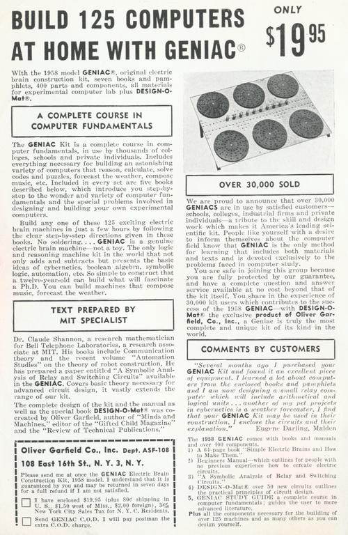
Final layout for the PCB that drives the 16 x 6 register display
I also test fitted the actual thyristor and resistor parts on the paper copy to be sure that I didn't make a stupid error. Those appear fine as well, giving me adequate clearance between physical parts. The thyristor, resistor, turret connectors and 1 pin headers all fit on the top surface of the board, while the 2 pin headers are placed on the bottom side with only their pins sticking up for soldering on the top layer. The only soldering required on the bottom layer is for the 1 pin headers. 

Since this is so tight, the order in which I solder everything will matter. I am not sure whether the resistor or the thyristor goes first, but the headers get soldered last. The turret connectors are fasted with nuts, not soldered, depending on mechanical pressure to make a good electrical connection. 

With this presumably ready to ship off to the PCB manufacturer, I started in on the two boards that handle the remaining lamps inside the pedestal, each an 8 x 6 matrix of possible lamp positions. In practice, the 1130 does not use all 48 positions on either board, but I could lay this out symmetrically and omit components on the unused positions.

I copied and cut down the schematic and PCB files, before making the remaining adjustments necessary. There is not a wide free area for the three turret connectors, thus I will have to be clever about where I place them to have a usable board that can fit in the spots required.

In fact, I noticed that part of the bottom row of lamps is unused on both boards, so I simply removed row 6 columns 4, 5, 6 and 7. That gave me plenty of room to move the three turret connectors and still have a small board that will fit side by side where it has to inside the 1130 pedestal box.

Small PCBs to implement the remaining lamps (other than the six major registers)
The pedestal box has a matrix of 5 x 5 plastic honeycomb units organized as two rows of seven blocks each. Horizontally, each hole may be used but vertically, only the odd numbered rows have lamps installed. Thus, the six rows of the panel sit on rows 1, 3 and 5 of the top honeycomb block then on 1, 3 and 5 of the bottom block.

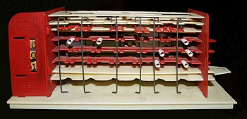
Honeycomb blocks (1 is missing in the picture)
There are a total of 35 lamp positions horizontally across all the blocks, but only 30 are active. The registers sit in the rightmost 16 spots (viewed from the rear of the machine), thus take 3 whole honeycomb blocks plus on position of the next block. One open position sits to the left of the last register lamp, which is open space to accommodate the edges of my big and little PCB boards.

One of the small boards implements six lamp holes, the leftmost honeycomb plus one hole in the adjacent one. My board covers eight holes horizontally, however, so my board sits across two more hole positions in that adjacent block.

The block has two remaining hole positions, that will remain free or have just a smidgem of the small board edges over them. The other small board sits over the next eight hole positions, en entire block plus two holes of the block shared with the end of the big board.

Counting from left to right, in the rear, for the 35 possible lamp columns implemented by the seven honeycomb blocks, we have my first small board covering holes 1-8, the second small board covering holes 11 to 18, and the large board covering holes 20 to 35. The edges of the left two boards have holes 9 and 10 open and will have no problem fitting side by side.

The edges of the middle (small) and right (big) PCBs have just row 19 open to accommodate them, but that is sufficient for them to fit side by side. There is 1" between the centers of the end lamps of the adjacent boards, but they have less than 1/2" of margin from the lamp on their edges.

I will remove the mini PCBs that are the original IBM mounting spots for thyristors and to which the bulb holders are fit, detaching the wires from the terminal blocks which feed them. This will be saved so that the machine could be restored to original condition if someone so desired.

The turret connectors arrived today, spurring me to purchase all the 2 pin sockets and header strips needed to finish the construction of the boards. I picked up paper straws, which I will use as a barrel to hold the miniature light bulbs soldered onto their 2 pin headers so they can be plugged into the sockets on the boards.

Next up, I shipped off the boards to the foundry, using PcbUnlimited.com to panelize them. I should get them in about two weeks. Nice high quality 4 layer boards that cost almost $250 including shipping.

I am excited enough about this that I will go out and begin removing the original holders right now. I do have to separate out all the bulb holders, because once I have the headers and straws I can remove the bulbs and begin assembling all the plug-in lights.

Alto event planning, work on IBM 1130 panel upgrade and on disk tool

ALTO DISK TOOL

I attended a meeting today at Computer History Museum to discuss holding an event to celebrate the Xerox Alto and other innovations, leveraging a few restored machines and many of the people who made those inventions. We also had staff from the museum, both historians and the live event producers, plus Marc, Ken, Luca and me for our restoration team.

Some of the people at the meeting who worked on these systems at PARC and are going to help with the upcoming event: Chuck Geschke (co-founder of Adobe), Doug Fairbairn (a founder of VLSI Technology), John Shoch (former president of Xerox Office Products Division and venture capitalist).

A number of the current staff of PARC were there too and will be involved. We expect to have the Alto we restored, at least two Altos restored by Al Kossow, a networked link to an Alto at Living Computer Museum, and hopefully Bruce Damer's machine which we are attempting to restore.

I did some diagnostic work during the brief time we had at Marc's lab today. I found that my synchronization between the various state machines involved in writing was not working properly, leading to a sector with nothing but zero output bits

I attempted to read a cartridge that wasn't archived properly earlier, but all records of all sectors had checksum errors reported. I used a scope to capture sector 0 on read of the cartridge in question. The data appears properly formatted so the issue is some regression error when I updated my logic.

IBM 1130 PEDESTAL LIGHT UPGRADE

I thought I had everything placed properly, it routed successfully and I worked my way through the minor manufacturing issues, such as silkscreen component outlines touching via hole pads. I was almost done when I spotted two light positions whose components were swapped around - register 2 (Storage Access Register) bits 4 and 5.

PCB layout - some swapped components to be corrected
While I could swap the input signal wires, it ruined the symmetry of the trace lines and complicated that section. I therefore planned to move things into their intended place and manually draw the traces to connect it properly. As you can see from the picture, it is a very dense board where the parts barely fit in place. 

Thursday, May 25, 2017

Building PCB design for IBM 1130 light enhancement, plus working on disk tool debugging

ALTO DISK TOOL

I think I have worked out some light modifications to allow me to trigger my disk tool for writing, without having an actual disk drive attached, such that I can capture the stream being written to debug any further bugs.

I was ready to make the changes, but had to find where I stored my FPGA boards in order to load the logic onto it. I spent a bit of time putting in the changes to help with testing tomorrow. We should have a good session tomorrow at Marc's home, collecting data to get my cartridge writing logic working properly.

IBM 1130 UPGRADED PEDESTAL LIGHT DISPLAY

I launched the PCB design software and began to tediously build the panel that supports the 16 lights each for the six registers (IAR, SAR, SDR, AFR, ACC and EXT). This board will have 96 thyristors, 96 resistors, 96 single pins for the signal inputs, 96 double pin headers for the lamp attachments, and 3 turret terminals to provide power, ground and lamp test voltages, capable of delivering 1A on AC and ground turrets when all lamps are lit.

The design begins with a schematic to define all the connections, which I built up first by drawing a single register of 16 circuits and then replicating that six times across the sheet. When I transfer this to the PCB for layout, I will have hundreds of parts to find and place in the correct location.

If I left the sequentially assigned part numbers, such as JP3 for an input pin or D34 for a thyratron, the layout would be extremely tedious and error prone. I took the time (considerable mind numbing time) to rename all the parts with a logical structure that instantly identifies which light position they implement. Thus, S103 is the input signal for register 1, bit 3. T311 is the thyristor for register 3, bit 11. R200 is the resistor for register 2, bit 0. and O415 is the 2 pin header for the lamp for register 4, bit 15.

With this, I can find and drag the parts to their desired locale on the PCB. The only parts with strict locations are the output (2 pin) headers for the lamp mounting. The power headers and the various signal pin headers just need approximate siting - signals near their thyristors and the power turret terminal in the right edge zone.

This first PCB, for the six registers, will be 8 1/2" wide and 4 1/4" high. The right hand 1/2" is the zone for the six double-pin power connections. The lamps are separated 1/2" center to center running left to right within a register, and the register rows are separated 3/4" center to center from top to bottom. The board has a 1/4" margin on three sides and 3/4" on the power connector edge.

The remaining lights in the pedestal will be covered by two identical but smaller boards, each hosting an array of six rows of eight lamps each. Some lamp positions are not implemented, depending upon the signals being displayed and the arrangement of the faceplate.

Image result for ibm 1130 pedestal
Faceplate - registers on left half, status at mid right and other data on right
One board handles the mid-right section that has the T and X clock states and various status lamps, while the other board on the far right covers the op code, registers, interrupt levels, and so forth. One design will produce both of the smaller boards, with the board sparsely populated to fit its role.

The schematic relabeling of the register board took many hours to complete, before I could lay out the physical board and place components. I wasn't done with the relabeling until the evening. Therefore, I am just beginning on the layout.

However, I found that spacing will be much tighter than I expected, because the spacing between lights is just 1/2" horizontally and 3/4" vertically. The SCR is more than 1/4" by 7/16" which fills a lot of the space between adjacent lights in the grid. The resistors and signal pins are easy to fit, but the SCR is the dominant factor.

I tried out a different organization to see if I can get the parts to fit in the tight grid. I rotated the 2 pin header from horizontal to vertical orientation. This allowed the thyristors to fit between the columns of lights and my 0805 sized resistor and signal pin will fit as well. I had to lay out an entire row across the top and the entire left column to ensure that everything fits.

The only unknown is routing. The path from the resistor and input pin is very direct to the thyristor, as is the path from thyristor anode to output pin. Further, the ground and AC voltage lines are on the inner planes of the four layer board, saving the need to route those lines. The only line that will be significant for routing is the lamp test signal.

It will take me another day to finish laying out all the components across the board before I can attempt the routing. 

Tuesday, May 23, 2017

Adjustments made to disk tool

Maker Faire took place these last few days and I was busy volunteering as an examiner for amateur radio license testing, for attendees who wished to get or upgrade their ham radio licenses. Since the FCC requires a ham license to transmit video from a drone, in addition to the usual reasons people become hams, we were fairly busy. I worked the first shift every day. 

ALTO DISK TOOL

While at the ham testing booth at Maker Faire waiting for the show to open to the public each morning, I did some work on the disk tool to clear up the synchronization issues when writing images to disk cartridges. Of course, this requires testing to validate but this looks promising.

I also tweaked the reading logic to be independent of recorded clock pulses from the disk drive once the checksum of each record is read and tested. The Alto switches from the disk drive clock line to its internal clock at this point, just as it uses the internal clock to count off the preamble time before it looks for the sync word beginning each record.


Thursday, May 18, 2017

Mostly testing and data collection tasks on the Alto

ALTO DISK TOOL

I stopped by the workshop in Marc's basement and did some testing with my logic. I discovered a problem in the way I load the shift register that serializes each word to be written to the disk drive. I am clobbering the data in the shift register before it has been written fully out, in some cases, which manifests itself when the sync word (x0001) last bit '1' does not make it onto the disk.

The challenge here are several independent processes with strong timing requirements that have to interface with my overall logic to write out a record. Another timing dependent activity is RAM access, taking multiple fpga cycles to complete, in order to fetch the next data word.

One machine is emitting clock bits every 600 ns and at the 300 ns point, midway in that cycle, it will emit either a 1 or 0 data bit. The serializer must shift out a bit to set it up for the first machine. The serializer counts down the 16 bits as they are shifted out, then emits a signal to get the next word.

My overall record-writing logic must load words when the serializer requests them, but also has to have read the data word from RAM in advance to allow it to feed the word on demand to the serializer. I issue the load request for the serializer as soon as the RAM read is complete, but that is before the prior word is fully shifted out since I have to do the reading in advance.

I am refactoring the logic again to get this cleaned up and will then have to test next week, after Maker Faire is over since many of us will be doing duty there.

ALTO RESTORATION PROJECT

In addition to the data capture I pursued, we worked on a few other tasks. I upgraded the ethernet bridge machine (on loan from LCM) with the latest code they sent. We made use of it to boot over the network and explore many functions and capabilities. The one we failed at was achieving a copydisk over the network, to read a cartridge in the real Diablo drive in the Alto and copy it to the bridge machine which is PC based.

Ken worked with his ethernet tool to check out and build up his protocol support. His code begins the network booting sequence for the Alto getting back the specific image request but is not yet able to send the entire image. He is able to connect as ftp users and ftp servers, but something is still going awry with building command lines the server will accept

Wednesday, May 17, 2017

Issues found and hopefully fixed in disktool writing, plus good day with the 1401 computers

ALTO DISK TOOL

Counting clocks and laying out the data bits into words was the key to spotting problems. Immediately, I saw a few issues in the stream I wrote. I have to work through the logic in the tool, instrument some signals to help me debug it with a logic analyzer and resolve these.

First, I see that the bits that looked correct for the header record were actually incorrect. The header record consists of the sync bit, two words of zero (32 bits of 0), and a checksum word of 0x0151, then there will be ten words of zero following it. 

The checksum on the disk is a bitwise XOR of each word with the running total, initially seeded with 0x0151. Thus, if we start with 0x0151 and XOR by 0x0000 twice, we still have 0x0151 in the running total. The checksum word on disk, 0x0151, is compared to the running total 0x0151 and we have a validation of the record integrity.

However, I found that I wrote the sync bit, only one word or 16 bits of zero, 0x0151, and a stream of zero words after. I dropped one of the two words of the header (0000 instead of 0000 0000). This coincidentally passes the checksum validation (!) thus giving the misleading symptom that my reading problems only occurred on the following label record.

To see why this still passes muster, consider the process in the microcode. After it finds the sync bit, it reads two words in and XORs them to calculate the checksum. It then reads the third word from disk and compares to the running total. Here is what happens with my abbreviated record:

  • Initial seed for checksum sets it to 0x0151
  • First word of zero is read, XOR leaves running total at 0x0151
  • Second word is 0x0151 since I omitted the true second word
  • XOR of second word with running total sets it to 0x0000
  • Third word read is really one of the zeroes that sit between records
  • Check of the third word - 0x0000 - with the running total 0x0000 yields equality
  • Checksum appears to validate integrity of the record
I have a miscount in writing out the data, omitting one of the header record words of 0x0000. That must be addressed, But wait, there is more! The gap between the header and label records should be exactly ten words of 0x0000 followed by the sync word of 0x0001 but the timing shows there are a few extra clock cycles or bits of zero in the gap. This must be addressed too,

Looking at the label record, which should be a sync bit, eight words of the label data, a checksum for the record and another gap filling set of ten words of zero, I find that the first data word is correct but the second is not right. Therefore, the problems are not simply a failure to write all N words of a record, but are worse. 

My logic is fetching words from RAM to fill a shift register, shifting the bits out serially to output each word of a record. Either I didn't fetch the second and ensuing words properly or there is some other failure in coordination between shifting, reading, loading and managing the record. 

The first word of each record comes out right, which makes the results on disk superficially appear correct. It is only when carefully counting more than 5000 clock cycles and laying out the words they represent that the problems are clearly visible. 

I think I fixed several of the problems through a refactoring of the write field logic in the disktool, but I also set up key signals to be monitored on the four PMOD connectors on the fpga board. I can hook these to the logic analyzer and debug more deeply, if what I see on the scope doesn't match what should be written.

IBM 1401 RESTORATION

I rebuilt four more of the power sequencing SMS cards today, replacing three resistors with two of different values and one transistor from type 26 to type 30. They were all tested in the Connecticut machine and performed perfectly. We now have both machines with two new cards in the sequencing gate, plus two spares placed into our inventory.

We seem to have a problem on one of the 026 keypunches which were converted from selenium rectifiers to modern silicon diodes. We think that at least one of the six diodes is malfunctioning, although the full wave bridge is working fine. More diagnosis needed to find and replace the pesky critter.

A new volunteer, Nora, is working on organizing all the parts in the workroom. It will be a delight to have everything well labeled and easily accessible. The challenge in front of her is formidable, as we have many boxes or bags that contain a huge jumble of components.

Imaging a few hundred assorted transistors in a plastic baggy, then multiply that by many such collections. Finding a part of a given type, such as the type 30 transistors I needed, is a painstaking process thumbing through everything. When Nora is done, we will have these sorted, separated and labeled.

One of the 1401 systems forgot how to stop today. A program would be started but none of the Stop buttons on the CPU or peripherals would cause it to stop the execution. Bill traced it to a failed Stop Latch and replaced the card. I will diagnose and repair the card itself next week and put it back into spares. 

Saturday, May 13, 2017

IBM 1130 panel schematic, Alto restoration progress

IBM 1130 PEDESTAL PANEL ENHANCEMENT

I decided to attach the circuit drawing for the replacement lamp driver circuit I am building, noting its similarity to the original IBM circuits although superior from a mounting and service standpoint.


Lamp driver circuit - lamp test switch shown at bottom


IBM 1130 circuit by comparison

ALTO DISK TOOL

Still not booting from the cartridge after I write it. Did read of the sector and captured on a scope. Now for extremely tedious counting and measurements to see what/if I did something wrong.

I centered the scope on some key pulses, such as the one bit that comprises a sync word, to get precise timings relative to the sector start, then other sets of pulses were interpolated from the grid marks on the scope face so that I can determine the timing with reasonable precision.

The clock pulses are in a train on the other trace below the data bits, one every 600 ns in a sector that 3,333 us long. That is a LOT of clock pulses and for long strings of zero words I have to count them. Each word is 16 bits therefore 16 clock pulses per word. For example, the separation between records in a sector is 10 words of zero plus a sync word with a single bit on. That is 176 clock pulses that have to be carefully counted.

Then, in the data words of a record, I have to carefully count clock pulses to divide out the data bits into words, before checking them against the file contents I tried to write to the cartridge. Checking 326 words in a sector involves accounting for 5, 216 clock pulses.

I spent the day Saturday capturing and recording the timings of the 1 bits, but was only beginning the checking of clock pulses to align them into words by the end of the day.

XEROX ALTO RESTORATION EFFORT

Yesterday we made progress on several fronts and dug into diagnostic information on others. The Digibarn machine was further cleaned and examined. The monitor that came with it is built for a Dorado, a later machine. It has a 6502 microprocessor on a board inside that multiplexes the monitor, keyboard and mouse signals over a bus using seven differential pairs with fast ECL drivers. That is very different from the connectors used with the Alto. Fortunately, we can intercept the signals from a connector inside the monitor and wire up our own cable adapter.

The capacitors to replace inside the power supplies have not yet arrived, so we didn't make any progress on that part of the Digibarn machine. Al Kossow warned us of a tantalum capacitor that often fails in the supplies, which we will also check before finishing the restoration of the supplies.

Ken's network tool passed several milestones, successfully handling echo protocols, telnet connections and ftp connections. The ftp protocol is different from the more commonly known protocol that comes with TCP/IP systems, but has similar goals. The client connects to the server properly, and command strings are mainly recieved and parsed properly, but the unit is not yet executing those commands.

With a bit of tweaking, we had the LCM ethernet bridge operational, which will be important to link together groups of Altos as we more are made operational. We did some network booting and communications, but didn't explore the file server or other utility functions. 

Wednesday, May 10, 2017

Finished up the upgrade of 026 keypunches, 1401 power sequencing, and built Digicomp I replica

CHM 1401 RESTORATION TEAM

I finished up the work changing out selenium rectifier stacks for silicon diodes in the remaining two 026 keypunches. It was a somewhat tedious job but done by lunchtime.

I managed to find another IBM 030 transistor and heatsink, which I put into my modified power sequence card for the 1401. This version of the circuit, discovered in the main 1401 ALDs but not matching the cards installed in the systems, runs much cooler. 

The original cards, used to validate a power supply voltage and activate relays in the powerup sequence, had pretty low resistor values biasing the transistor, one end of the divider tied to a 30V reference voltage and the other tied to the power supply being validated. It burned almost 4W in the divider, all the time, with the two resistors sitting flat on the card with no airflow around them.

The result is scorched card material, sizzling hot resistors and periodic failures of the cards. The alternative schematic I found replaces a 600 - 56 divider with a 3000 - 220 divider and puts in a different transistor number with a small heatsink. The circuit runs about 25 times cooler.

Now we have both of the two sequencer cards in the German 1401 converted. As soon as Glen, our wizard finding parts in the workshop, returns and finds me two more, I will convert the two cards for our other 1401. 

DIGICOMP I KIT

When I was young, in the 1950s and early 1960s, the only 'computer' access available to virtually any youth were machines designed to teach computing principles but built with mechanical, switch and light bulb and perhaps a few relays on the high end options.

Geniac (sometimes called Brainiac), consisted of a large perfboard with six large round perfboard dials, where the holes would be filled with screws and nuts, so that the round dial's screws contacted the screws on the main perfboard underneath. One wired between the various screws to implement logical functions, ultimately illuminating one or a few small flashlight bulbs to indicate the answer. 

geniacamazing

Digicomp I was a plastic kit with three "flip flops", where a lever was turned to implement logical functions. It was programmed by placing cylindrical plugs on the flip flop edges, then when the lever moved the boards, some vertical wire rods were pushed and in turn shoved sliders left and right. The outcome was read through a slot on the left, consisting of the three binary digits that were the current flipflop state.

The Minivac 601 had eight pushbuttons, eight relays, eight slide switches, and eight light bulbs, which could be wired up to implement very simple logic functions. In addition, it had a rotary dial powered by a motor, which acted as a rotary switch. You could program it to run the motor and stop when the dial reached the answer position, thereby energizing or dropping one of the relays. 
Minivac 601.jpg
As you can see, these were incredibly simplistic virtually toys. Unless you were one in a million and had some access to an actual computer, this was all you could get as a 'personal computer' in those days. The Minivac 601 was designed by Claude Shannon, had some cachet, but was also inordinately expensive for a youth, as its price was the equivalent of over $675 today. 

I had a Geniac and a Digicomp I, plus I knew a well off schoolmate who had a Minivac 601 that I could look at longingly on occasion. My Digicomp, being rickety plastic, fell apart long ago and was just a memory, but I discovered someone selling a reproduction kit, using cardboard and foamboard rather than plastic.

I just assembled my Digicomp I replica and spent a bit of time 'toying' with it. Three flip flops and a limited number of ways to make them interact - pretty limited but it can count modulo 8 and do some very simple tricks. 

My high school had a 1620 computer but the conditions for attending the related class didn't work out for me, so it wasn't until a couple of years later than I had a chance to get hands-on time with an IBM 1130.

Not just keypunch decks of Assembler or Fortran to have run in a batch, like most users, but if I was willing to show up at 2AM when the batch processing was complete, I could work by myself for the rest of the night. Hand stepping code and quick turnaround of coding errors helped me appreciate computers to a sufficient depth that I changed the trajectory of my life and moved into the computer field, rather than working on space programs. 

Tuesday, May 9, 2017

Digging into remaining Alto disk mysteries, prototype successful for IBM 1130 pedestal panel light enhancement

ALTO DISK TOOL

I have two unresolved questions concerning the Alto disk behavior:

  1. 1) There is a delay at the start of the sector that appears as a long wait in the logic analyzer trace but I don't know what causes this.
  2. When the Alto does an update, it reads at least the header record before switching to write mode to write the data (and optionally label) record(s), but I don't see how it retains the 10 word gap that exists with pure write or pure read. 

I am studying microcode and thinking about this, hoping to resolve #2. I can deal with issue #1, if I can't understand its cause, either by writing without the padding if an Alto still reads it, or by injecting an arbitrary padding myself.

The flow of the microcode is to loop through four times in the lifecycle of a sector. First is a quick initialization pass. The next three are for the header, label and data records respectively. Most of the flow is the same, but there is a conditional branching construct based on the record number being processed that picks up the unique values related to the record being processed.

The other important conditional branching constructs are RWC and WR. The first changes the path depending on whether the operation for this record is a read, check or write. The second changes path depending on whether a read or write line operation is active.

The microcode sets up a countdown loop, called a preamble, at the front of each record. It is 29 words long when writing zeroes in front of the header record and 18 words long of ignoring input for reading that same record. The preamble for the label and data records is 4 words of zero when writing and 5 words to ignore when reading. The postamble of all three record types is six words when writing and four words when reading.

Thus, we write all three records in a sector with 29 zero words, the sync word, the header record, six postamble zero words, four preamble zero words, the sync word, the label record, six postamble words, four preamble words, the data record and six postamble zero words.

When we read that record, we skip over 18 words, then start reading but waiting until we see the sync word. That would be in roughly 11 more word times. We read the header record and read four of the postamble words but don't look at them. The next record begins by skipping over five words worth of time then reading while looking for the sync word, which takes one word of zeroes before we see it.

This all works because the reading process involves 9 words in total across preamble and postamble, while we wrote 10 during the write operation. That means we skip over one more word of zeros before seeing the sync word.

Reading the microcode for an update operation shows timings that don't make sense. The header record is always read, so skip 18, look for sync, read the record, and read but ignore the next four zero words as a postamble. Now, however, when we switch to the label record which will be written, the logic will write out four words of zero as a preamble. It then writes a sync word and the label record itself.

The inconsistency is that the gap between the end of the header record we just read and the label record we write has eight words of zero before the sync word, not ten like occurs with a pure write of all three records. Yet, the reading logic will consume nine words before it looks for sync. This means it will gobble up the sync word as the last of the nine words, thus failing to sync up.

It doesn't make sense that only eight words will be between the records after an update but ten otherwise. I have to ascribe this to something subtle I don't understand in my interpretation of the microcode and its likely execution path.

To handle issue #1, I dedicated slide switch 3 to add an 82 us delay at the start of a written sector when the switch is on, otherwise we write the 29 preamble words immediately. I can experiment with the effect of adding this, to see whether the Alto can boot or read packs that I have written in either case.

As I prepare for a testing session on Friday, I expect that I will be able to write a cartridge that can be booted and read by the real Alto. Whether this requires the mystery padding words or not, this will allow the tool to both read and write cartridges properly. The ability to update just the label or label plus data records is still untested and in great doubt.

IBM 1130 PEDESTAL PANEL ENHANCEMENT

I looked closer at the SCR modules used by IBM and found that they do NOT have isolation diodes as I would have expected. Instead, IBM places a 6.2K resistor in line with every system signal input to the modules and has a 6.8K resistor internally to the module in line with the lamp test input.

My prototype circuit will involve a series resistor to limit current into the SCR module, which hopefully will work safely with the existing 6.2K inline resistors since it will be infeasible to replace them. I could augment them if I need more resistance, however.

I could play around with an alternative that uses a diode to isolate the lamp test input, driving the entire panel worth of SCRs with a single 6.8K resistor (or whatever value the SCR needs) fed through those diodes.

My testbed consisted of a 6.3VAC AC power source (not quite the 7.5V of the IBM system but good enough as a proof of concept), a variable DC source set to 3V to mimic an SLT output level, and some point to point wiring across the scr, resistor and other components as I tested it. I also tack soldered the lamp onto the module.

The circuit worked great. Bulb bright, with the actual AC voltage measuring a tad over 7V so even better than expected. I studied the IBM lamp test and lighting circuit wiring more closely and discovered that the resistors will work just fine, avoiding the need for diodes. The trigger voltage was dropped to near 1V and still turned the lamp on brightly.

The way the IBM circuit is wired, the SCR gate is tied to a voltage divider of a 6.2K ohm resistor up to the system signal line and a 6.8K resistor to the lamp test line. Lamp test is held at ground unless the switch is momentarily activated, at which point it is connected to +3V.

The input from the system logic will be either up near +3V if logically on or down near 0V if logically off. The resistor divider network will take that signal down to ground through 13K of resistance, drawing less than a milliwatt of power and less than 1/4 milliamp of current. The midpoint of the divider presents a bit more than 1.5V, which works just fine to switch on the SCR.

If the lamp test is connected, the +3V on the lamp test line is either divided by the near 0V from the system logic line or up at +3 if both are active, in either case firing the SCR. There is no issue with having multiple system logic lines connected through 13K to ground as this is a normal load for an SLT circuit.

This saves me a bunch of money, as I only need a 6.8K resistor and an SCR for each bulb and I will have a completely suitable lamp driver for the 1130. The signal lines connect in directly to the gate of the SCR, the cathode is at ground, the 6.8K resistor runs between the gate and the lamp test line, and the anode of the SCR runs through the light bulb to the 7.5 VAC that swings above and below ground.

I have to plan for 155 lamp circuits - 96 for the six major registers plus another 51 status signals and 8 CE lines that can be wired to monitor any 8 logic levels in the system. With some extras as a buffer, hat comes to about $100 in SCRs, perhaps another $100 for the circuit board and miscellaneous components such as resistors and headers.

A project that is well worthwhile given the headaches it saves. I placed the order for the SCRs and resistors today and will begin designing the circuit boards soon.

Monday, May 8, 2017

Introduced important fix to the Alto Disk Tool, began prototyping for 1130 panel upgrade and worked on CHM modifications

ALTO DISK TOOL

I reengineered the tool to add the extra delays I am seeing in packs that boot properly. Initially, the tool will write zero words equal to about 82 us of delay before it starts the 28 preamble words of zero. In between records, the tool will insert two extra words of zero.

The microcode uses constants for the delay words between records, but the actual execution takes one more loop than the value in each constant. Thus, if a constant of 4 is described, the microcode does this task five times. It was easy to overlook this when interpreting the microcode listing, but the logic analyzer makes it clear.

I don't think the initial delay is critical, as the Alto did read the header record of the sector correctly before stumbling on the label and data records. However, the extra two words between records is essential. The way an Alto moves between records ensures that it has already passed the sync word I wrote before it starts scanning for it, thus guaranteeing a misread.

IBM 1130 PANEL UPGRADE

I received my sample SCR and diode devices, allowing me to build a prototype to test driving indicator lamps with a 7.5 VAC supply and logic signals conforming to IBM Solid Logic Technology specs on both the signal and lamp test inputs. If this works well enough, I can design the circuit board to implement all the light positions in the 1130 pedestal box.

COMPUTER HISTORY MUSEUM MACHINE UPGRADES

I worked with Bill Newman who was applying an upgrade to four of the 026 keypunch machines, replacing the original selenium rectifiers with modern silicon diodes. We are doing this to avoid the noxious and slightly toxic fumes that Selenium rectifiers emit when they fail, as a safety measure.

We completed two of the four machines completely, meaning replacing the bridge rectifier as well as six separate selenium stacks used as diodes. Two other machines had their bridge rectifiers replaced, but we didn't have enough single diodes to replace the stacks with six diodes apiece. We will complete those on Wednesday.

I brought in a supply of 220 ohm 2W resistors to refill the empty drawer in our workroom and to complete the modified power sequencing SMS card for the 1401 systems. The original cards that sit in the machine have a pair of resistors that get extremely hot in operation, scorching the actual card underneath.

A 1401 power sequencing schematic shows an alternate set of components that run much cooler. I changed the card to match. This involved three new resistor values to drop the bias current, reducing the power dissipated from 3+ watts down to fractions of a watt, in conjunction with a changed transistor type.

We placed the modified card in the machine and verified that it successfully sequences power up and down. Next, I will build another such card since the 1401 uses a pair of them. The next card was all but complete, except for the IBM type 030 transistor, which I couldn't find in our stocks.

Saturday, May 6, 2017

Working on Digibarn Alto, disk tool and ethernet bridge

ALTO DISK TOOL

I may have found some differences that could account for the failure to boot/read the disk cartridge that was written by my disk tool. Changes made, but I also set up some diagnostic output that I can use to closely examine the output of my tool while writing if it doesn't work first time.

The changes were not sufficient to allow a cartridge I wrote to be booted. See below for more on this.

XEROX ALTO RESTORATION SESSION

We have a loaner ethernet gateway built by the Living Computer Museum which will allow us to access a file server in that box, share with other Altos including our unit, and do network bootups. In addition to loaning us the gateway, Al Kossow loaned us the cables and transceivers to connect to the unit.

I brought my disk tool changes to see if I can write a pack that will boot on the Alto, or at least collect more definitive forensics if it doesn't work right away. Ken brought his ethernet gateway as well. Bruce Damer brought along his Alto system in order to see whether it is working or what might be wrong. Of course, we had to visit his Digibarn collection in order to help him load it up.

Bruce's Alto had been visited by mice while in the barn, so the first order of business was to wash off all the boards and remove droppings from inside. We discovered that a few key parts are missing from the unit, including the memory addressing board, the jumper cable for control ram, and the video display cable.

We couldn't test his display as the cable connection is different from the unit on our Alto. He had brought a disk drive along but we found a label inside it - "smoked" - which may indicate serious problems. No obvious signs of damage, but he will bring other drives next week.

We pulled the four power supplies out of the machine and brought them to the bench for testing. One large supply provides +5V with both high current (60A) and low current outputs, two units provide 15V up to 12A of current and one provides 12V with up to 15A of current.

One of the 15V units came up perfectly, tested right up to its 12A load limit and with acceptably low noise showing on the scope. Another 15V unit had a missing fuse, which we replaced but it promptly blew the new one. The 12V unit refused to delivery any output power. The 5V supply also delivered no output at either the high or low current connections.

We opened the 5V supply and found a blown 12A fuse inside. We didn't have a spare 12A fuse but decided to remove the filter capacitors and check them, as they are the most likely component to have failed. Three of the four capacitors failed miserably and the fourth was way off spec, meaning they must be replaced.

Once we install new capacitors and a new fuse next week, the last check before power is applied should be the rectifier diodes, to be sure they didn't fail due to the capacitor problems.

Moving on to the LCM ethernet bridge, we installed it. It consists of two ethernet transceivers, one cabled to the Alto and the other cabled to the special board in a small PC that houses the bridge. A section of ethernet, terminated at either end, is hooked between the two transceivers.

We powered up and started the software as outlined in the instructions, but were unable to ping the unit nor able to netboot from it. We didn't have time to determine where the problem lay, partly because we weren't fully familiar with the unit. Next week we will look to this.

My diagnostic outputs on the disk tool allowed me to watch the signals I was producing when writing to a disk cartridge with a image of a games disk that works fine on the Contralto emulator. They matched exactly what I expected to produce. Once again, the Alto wouldn't boot from it.

I then took three good cartridges, ones that were written on various Altos and that booted fine, watching what I could read from sector 0. I discovered two big discrepancies from what we expected to see, indicating that the spec to which I am working is not correct.

First, the initial sync word for the header record of the sector should, per the spec, occur 28 word times after the sector started. That would be around 280 us or so. On the three cartridges I tested, this happened at 415 us or slightly later, a big discrepancy.

Second, the time from sync word to sync word is longer than I expect by two extra words of zeroes. From header record to label record, I should see two header words, the header checksum, five postamble words and three preamble words for a total of 11 word times. Instead the delay is 13 word times. The label record to data record gap should be 17 words long but was 19, also having two extra words of zeroes.

The logic analyzer traces I have when the Alto read a cartridge successfully don't show the extra time,neither the source of the 130 us or so of initial delay nor the occurrence of two extra words of zeros between records.

As a practical matter, I will modify the tool to push the first sync word back to the 415 us region and to stick two extra words of zeroes between records.  Next week we can see if this produces a properly bootable cartridge.

Even so, I want to understand how the real world disks can be so far off what the microcode seems to produce. Maybe I can find clues in the logic analyzer trace or the disk controller hardware.

Tuesday, May 2, 2017

Progress on Alto disk tool, planning improvement to IBM 1130 display panel, and helping move a 4331 system

ALTO DISK TOOL

Working through the logic analyzer trace line by line, decoding and understanding the microcode of the Disk Word Task and its related hardware, led to the discovery that some of the comments documenting the microcode used numbers that appeared to be decimal but were in fact octal values. 

Thus, when the DWT writes a sector, it begins with 34 words of zero (in octal) which is only 28 words. My spec for writing the sectors had a few such constants wrong. Working through it all, I have an updated spec and am in the process of adjusting my fpga logic to fit that. 

To understand this well, I had to master the Alto microcode and controller hardware so that I know exactly what is happening on the disk. I had a logic analyzer trace while the Alto read a sector, which I used to ensure I knew the exact sequence and timing of the operations.

I didn't have a corresponding trace of a disk write, but I mocked up a copy of the trace, changing each instruction which varies during a write instead of read. It confirmed my newly corrected spec for the disk format and operation. 

IBM 1130 PEDESTAL DISPLAY PANEL IMPROVEMENT

On the IBM 1130, a pedestal above the console typewriter contains about 150 incandescent lamps behind a smoked plexiglass faceplate, used to report on the values in key registers and system state information. Any time a bulb burns out and needs replacement, the design of the pedestal turns this into a long, tedious and frequently futile effort to end up with all lamps working correctly. 

Lamps pushed onto PCB boards
Honeycomb that the bulbs must fit into
I conceived of an alternate implementation for the insides that would preserve the incandescent bulbs, SCR control of the bulbs from a 7.5 VAC supply, and lamp test functionality, yet would allow for fast and easy replacement of any future failed bulb.
Boards pushed into the honeycomb - all 16 bulb sockets must align perfectly
I will replace the long shallow PCBs used by IBM. These contain an SCR module and have two pins to push into each light socket. The socket is in turn pushed into the honeycomb. The stiff power wires on the left or right end of the board, plus the 16 yellow signal leads running to the SCRs, make it extremely hard to maneuver the board and all its sockets into place. 

Instead, I will build one wide and tall PCB that is oriented in the plane of the honeycomb (top to bottom, left to right but not front to back). It will have a socket in place for each of the sixteen lamp positions of the existing boards, replicated so that the one new board replaces the six rows of old boards. 

The lamps used by IBM have bare wire leads coming out of the glass envelope. They are inserted into a plastic socket which has two cylindrical metal openings at the rear for insertion of pins. One of the pins for a light is fixed on the front of the SCR module, but the other is attached to the PCB with a looped pigtail wire. The pigtail wire can't be easily pushed into the lamp socket. 

Bare wire lamp inserted in plastic socket
pigtail wires
SCR modules on board
If the wires from the bare bulb extend out of the side of the plastic socket too far, they can short to adjacent sockets, which results in a block SCR module. This module has two diodes as well as an SCR, to provide individual firing of a lamp from the signal coming in by yellow wire on the back, and also bulk firing of all lamps from a 'lamp test' signal fed to all modules simultaneously. 

If the pins are slightly bent, the socket will also be bent. Since the pins must be press fit into the socket but the socket must also be press fit into the honeycomb, the result is a board with 16 sockets all slightly skewed from the position needed to push into the honeycomb. Now imagine the stiff wires that are in place and you see why it becomes quite challenging to fit even one PCB into place, much less 12 that are very close together. 

bulb sockets pressed into honeycomb
Roughly 150 lamps more or less inserted into place
My solution will allow two large PCBs to swing out from the left and right sides respectively, giving access to plug in my new lamp sockets for each failed bulb. The right side PCB, viewed from the angle of the picture above, will have six rows of 16 bulbs stacked vertically, with all the yellow wires you see running to pins on the back of the PCB. It is anchored to the ground, 7.5VAC power and 'lamp test' line at the right edge, those wires acting as its hinge. The left side will hold the remaining lamps. 

Instead of the plastic sockets used by IBM, I will use a two pin header strip, with the bulb leads wrapped and soldered to the pins. A header socket on my PCB will be in each place where a lamp should sit. I can quickly pull off one and put on a replacement just by swinging the PCB backwards. The bulb itself will stand off the PCB because of the header strip and then its own length, so that it will be deep inside the honeycomb when the PCB is pressed against the back of the honeycomb structure. 

Instead of the fairly large IBM SCR modules, I will use modern surface mount SCRs and diodes placed on the rear of my PCBs. I have ordered the parts I think will work, in order to build a prototype and do testing. My method will replace the plastic sockets and narrow PCB boards with their SCR modules, but preserve everything else inside the pedestal. It could be returned to original condition if a new owner wished to do so. 

MOVING AN IBM 4331 MAINFRAME SYSTEM

A fellow collector bought a 4331 system, along with a full complement of peripherals, but had to move it roughly 150 miles to its new home near Grass Valley, California. I agreed to help him move it this past weekend, along with a few other helpers. About 9000 pounds of boxes, cables and parts were involved in the move.
Image may contain: indoor
Loaded truck
The system included the following peripherals:

  • 2540 card reader/punch
  • 1403 N1 line printer
  • four spindles of 3340 disk storage
  • two 3420 tape drives
  • 2821 and 3803 control units
  • four 3278/3279 terminals

Image may contain: indoor
4331, 3340 spindles, 3420 tape drives
Image may contain: indoor
3420, 2540, and 1403