Friday, October 31, 2014

Still battling the keypunch, stalemate tonight, plus more assembly of SAC interface boards

NEW KEYPUNCH INTERFACE DEVELOPMENT

After going over the inside of the keypunch and bending various SMS socket pins and relay panel pins to ensure there are no unintentional shorts, the keypunch appears to be working just fine by itself. I finished wiring up the new keypunch cables I began with better, more secure connectors and larger gauge (lower number) wire. I dressed it well along the panel and made the cable much more bulletproof and production level.

New reader cable DB25 plug - rugged wire bundle

Reader and Punch cable wiring dressed in place on back of wire relay gate inside keypunch

My reader (white) and punch (red) cables ready to plug into the interface box
In addition to replacing the cables and dressing them along the keypunch relay gate, I wired the power brick into the power supply so that it is switched on with the main keypunch power switch under the table. Finally, adding a DB9 extension cable to run up out of the machine, I now had the means to put the box inside the keypunch ready to close up the interface cover once debugging is complete.

Power brick cable converted to lugs to attach to the 029 power supply
Testing resumed but the keypunch is stuck in its state of refusing to recognize a card was registered. I will check over my wiring a bit but I am beginning to suspect this is just erratic operation from relay contacts that still have a bit of oxidation on them. However, I will also recheck the wiring to be sure it is correct.

SAC INTERFACE FOR ADDING PERIPHERALS TO THE 1130

I assembled more receiver and driver circuits onto the board today. I was able to finish one board and have three more to do. It is slow going to make sure I do it correctly. It has the +5V, +3V and ground power lines attached but does not yet have input or output leads.

One completed board for SAC interface, 12 drivers across top and 12 receivers across bottom

SCANNING COBOL PROGRAMMERS GUIDE MANUAL

Several manuals are not available on bitsavers or other digital archives, but should be. I slowly (and I do mean slowly) get the pages scanned in between other activities. This manual with more than 180 pages has taken three days elapsed time so far and I am still only at page 150. I don't usually comment on the scanning but realized it was completely sub rosa if I didn't.


Thursday, October 30, 2014

Very light day working on the system

Between heavy work obligations and an afternoon at the dentist, I only had two hours to spend in the workshop today. Still, I did make a bit of progress.

NEW KEYPUNCH INTERFACE DEVELOPMENT

I removed the added wiring inside the keypunch and began to wire it with the new preferred push on connectors, on the assumption that the old connectors were bridging to the wrong wires because they weren't very secure. While I was at it, I used larger diameter wire which I will install on a DB25 connector.

With all the wiring disconnected, the keypunch was still misbehaving. It worked fine with a card registered in the punch station but once there was a card registered in the read station as well, the card lever relay won't activate so punching or spacing is not possible. At least I now know this isn't a flaw in my interface design.

As soon as this is debugged and repaired, I can resume testing of the interface. While I am working on the keypunch wiring, I am also replacing the read cable connections as the pins I used are also insecure, very wide and exposed at the top where they can touch other pins.

SAC INTERFACE FOR ADDING PERIPHERALS TO THE 1130

I soldered a few more driver and receiver circuits onto the board, until it was too dark to see on the outdoor work table I use for assembly.

Wednesday, October 29, 2014

Successfully booted DMS2 from the internal disk drive and began building the SAC interface hardware.

Very busy with tasks from my day job, but I was able to grab a couple of hours with the system and made good progress in that time. starting manufacturing the logic/voltage conversion hardware that will interface the Storage Access Channel cable from the 1130 to TTL logic.

1131 DISK DRIVE RESTORATION

I checked over the cold start card data I had written down, spotted a couple of transcription errors and fixed them. After toggling the eighty words into core and readying a disk cartridge with the DMS2 monitor installed, I booted up the 1130! I head it seeking and reading multiple sectors and then drop into its I/O wait condition. The IAR read x002A and the accumulator (ACC) has x6000 which means the 1132 printer is not ready - exactly what would happen since I didn't have the printer powered up.

This is a very strong test of the system, both the 1131 processor and the disk drive, much stronger than the diagnostics I have been able to toggle into the machine so far. Once I have either the 1053 or the 1132 ready to print, I can run even more - DMS2 can be set to print on the console printer as an alternative to the line printer, plus the input commands can be rerouted from the 1442 card reader to the keyboard. I would need to have the 1132 appear ready, even if the hammers are not causing readable impressions, just to allow DMS2 to be ready to read. Then, I would have to nurse one card through the 1442, // TYP, which redirects input to the keyboard.

That would allow me to type in some job control (monitor) and supervisor cards. I could run programs, at least those that will allow all its critical input to come from the keyboard or keyswitches and don't need to print or read cards.

CHI INTERFACE AND DISK DRIVE

Until the disk heads can be thoroughly cleaned and inspected, I will not be putting any cartridges into the Diablo drive. I may experiment a bit to get sense DSW to respond for the disk drive and line printer device address that the interface implements.

I am not sure what addresses it uses, although the printer is called a 1405 which implies it may use the same area code as the IBM 1403 printer. Similarly, I expect the diablo disk to appear as one of the standard addresses that are used by DMS and the disk oriented utilities.

NEW KEYPUNCH INTERFACE DEVELOPMENT

I am not happy with the security of the connections put onto the SMS socket pins, suspecting these are leaning over, shorting together wiring to cause the balky behavior of the keypunch. I found some push on connectors that fit much better than the current ones I installed. Once I rewire this with the improved connectors and am satisfied, I will go back to the testing.

SAC INTERFACE FOR ADDING PERIPHERALS TO THE 1130

All my supplies came to day and I started construction. I slightly modified my plan for the board layout in order to make assembly easier. Now, each board will implement twelve drivers across the top half and twelve receivers across the lower half. I have built 25% of one board so far, before the light faded outside where my assembly table was set up.

Top shows three driver circuits, bottom has three receiver circuits

The circuits are packed tightly together, each requiring five vertical columns with the input at the leftmost column and the output at the rightmost one. The horizontal power strips are +5V and ground, but the receiver circuit also needs +3V which is an SLT requirement. The +3V will connect to the number two column of each five - you can see the open hole at the top  and near the bottom of the second column, where I will daisy chain the +3V down to a connection point at the far right of the board.

I have the parts to assemble circuits for all 77 signals that are carried on the Storage Access Channel interface. This will require four boards, whose total capacity would be 96 signals if they were needed, with twisted pair in the SAC cable hooked to these circuits. The TTL side of these circuits will be wired to a high density connector which I can use to connect other logic into this voltage conversion interface. 

Tuesday, October 28, 2014

Keypunch interface stubborn issue, SAC receiver circuit working, and testing the CHI interface/disk

NEW KEYPUNCH INTERFACE DEVELOPMENT

I wired diodes across the relay contacts in my box in order to absorb any induced back EMF from the opening of the coils. Electrically it would be more ideal to install these at or close to the punch solenoids in the 029, but we are trying to keep the keypunch modifications to a minimum. However, the small gauge wire connecting to the interface box will have to absorb the current spike flowing through the diodes.

Diodes added across relay contacts in order to quench back EMF from keypunch coils
With the diodes installed, I hooked up the box but found that the machine was not recognizing registration of a card even initially, with no attempts to punch. I will have to troubleshoot this to understand what is blocking registration.

I made up the dummy plug and verified that the keypunch works properly with the interface disconnected. Therefore, there is no damaged component in the keypunch. I hooked up the punch cable to my box, leaving all other cables including power disconnected. The keypunch worked properly one time with cards but after a clear cycle, it was again failing to recognize when the next card was registered.

Dummy plug for punch cable when box not attached to keypunch
This tells me that something in my static wiring is causing this problem - the wiring that is linked through relay contacts is somehow causing a problem - the relay contacts being open. It may be a wiring issue or a short in the connectors or something else, but I have to diagnose this before the box can be tested further.

I tested every wire going into the box from the punch cable and they were all infinite resistance to each other, except for the pair for multipunch pole 2 which are normally closed. I ran the keypunch with the dummy plug for a while, then plugged in the punch cable but otherwise had nothing connected to the interface box. This worked well for about five or six cycles of registering, spacing and clearing cards.

I then plugged in the power brick connector (but no AC was hooked to the brick), which locked up the keypunch on the second cycle. Very odd. At this point I have to suspect that a connection is intermittently shorting somewhere in the SMS block, so that small movements of the cables introduce the error.

CHI SAC INTERFACE, DISK CONTROLLER AND DIABLO DISK DRIVE

I powered up the CHI interface electronics and they came up cleanly. Looking over the cards, I came to the conclusion that it appeared likely to be working properly. As I result, I will cable this to the SAC interface and give it a try later tonight or tomorrow.

CHI interface looking good, decided to begin testing it
The interface came up fine and the drive loaded a pack I was willing to risk. I found a slight darker mark where the head was riding on the disk. I will inspect it in the sunlight to see whether it damaged the pack, but the heads must be cleaned at a minimum before I put any other cartridges into the drive.

Superficially clean drive, but some marking on a cartridge where the heads flew

SAC INTERFACE FOR ADDING PERIPHERALS TO THE 1130

I picked up the solder this morning and rewired the demo receiver circuit, which is hooked through a transmission line (I twisted wires together from the driver output and from the receiver input, then connected those twisted pairs temporarily). This is intended to verify that TTL input signals to the driver will be properly reflected as TTL outputs from the receiver, as well as my verification that the voltages are at appropriate levels in both states.

The circuit worked perfectly. I varied resistances to ground on the TTL input to the driver to see at what voltage it would switch between on and off. It will recognize a logic level 1 down to .1V but is off somewhere above .066V, well within the specifications for the logic I will use to drive signals towards the 1131.

Driver circuit on top and receiver circuit at bottom - working perfectly
Now that the circuits work with each other, I will temporarily hook the receiver up to one of the SAC output lines and the driver up to one of the SAC input signals, in order to prove these circuits work with the IBM SLT logic cards. I chose interrupt request and the corresponding interrupt level status as the signals on the SAC interface, as I should be able to see the request mirrored on the 1131 console and the status of the interrupt level on the panel mirrored at the TTL output.

I lieu of testing this, I powered up the CHI interface and disk drive (see above). I may do some XIO tests to determine how the CHI interface is responding (and to what addresses), but the important testing will be with my circuits once I move on to try them with the SAC.

I went ahead and ordered the transistors, diodes and resistors I need to implement the full interface which will give me TTL logic on my side and for the other side it will deal with the 1131 SLT transmission lines coming out of the SAC interface. I expect to have all the parts by the end of tomorrow, thus doing the assembly on Thursday and Friday.

Monday, October 27, 2014

TTL to SLT driver circuit working well, plus solid progress on the keypunch interface unit

1053 CONSOLE PRINTER RESTORATION

I have a good new belt for the 1053, although I know that installing it means partly disassembling the operational shaft and possibly having to redo all the settings when I put it together. I will stall a few days before starting this odious task.

NEW KEYPUNCH INTERFACE DEVELOPMENT

I studied the schematics for the 029 Keypunch and read the theory of operations manual until I figured out what is going wrong - the failure to register a card and allow punching that crops up after some time using the new interface. It is the multipunch key implementation I designed.

When the multipunch key is depressed, the keypunch will drop the alpha relay, putting the keyboard into numeric mode which does not allow space, A or Z keys to be activated (they have no numeric or shifted meaning). It also sets up the machine to pick the multipunch relay once the first key is pressed and to interlock further escapements (advancing columns).

The key on the 029 consists of two switch sections - one pole is normally disconnected but when pressed will route power to the multipunch relay. The other pole is normally connected to the circuit that holds the machine in alpha mode unless the numeric key is held down. When multipunch is pressed, it opens the line to the alpha relay, having the same effect as if the numeric key is pressed.

I only implemented the first pole, latching the multipunch relay but not switching to numeric mode. This resulted in the funny behavior, I theorized. I can take the two wires and relay currently used for the Clear switch and use them as the second pole of multipunch. Clear was not an essential function, it was a 'freebie' added because we had a spare relay.

However, the way the wiring works, we must be in series with the multipunch key second pole, All the other interventions are parallel, meaning if the cable is removed the keypunch operates normally, we just close a parallel set of contacts to the original key when we remotely operate it.

Due to the circuit layout in the 029, if we were to act in parallel to the numeric + multipunch pole 2 switches, we would block it from going to numeric mode - a failure. If we insert our relay in series so that our relay is normally closed, it will work properly and kick the machine to numeric during multipunch, but if the cable to our box is removed, the machine stays in numeric only mode - a different failure.

I can't see any clever way to implement this that is independent of the cable, unless I put a double pole relay down inside the keypunch to activate multipunch remotely; pole one in parallel with the key pole 1 and pole two in series with the numeric + multi pole 2. That would let me use one pair of cable wires to activate multipunch remotely, but it means additional changes must be made to a keypunch before it can be hooked to the interface. The upside is that we get our freebie Clear switch back because the relay and two wires are not needed - one circuit fires the remote.

The other option is a dummy plug that is put on the cable when it is not hooked to an interface box, the dummy plug bridging the circuit that is in series with the numeric + multi 2 switches. This requires less hardware but the user must remember to keep the dummy plug in place when the interface is not attached.

I chose the last method, rewired my keypunch and made a dummy plug up. This does not  preserve the two wires and relay for the Clear switch; we need it for pole 2 of multipunch. It has some rewiring necessary but that will be the normal instructions for modifying other keypunches.

Example of a dummy plug - although this is the wrong polarity. Need a male plug.
I put the modification in place, hooked up the interface, but I am still seeing the same problem - won't recognize card registration or allow punching. Letting the keypunch sit for a while and it works fine, but once I punch through the interface, the problem resurfaces. This happens with or without the read cable attached.

As far as I can see from the schematic my wires should be totally isolated from the other wiring, with relays connecting the circuits to fire various punch, space or release solenoids, and only one input which is my own magnetic reed switch with no wiring in common.

I have one small problem with single letter verb mode (i.e. allow M instead of MODE) that I will clean up, and it seems my parsing, storing and manipulating binary mode characters is flawed. However, my multipunch key functionality now works perfectly.

At this point, I suspect it is back EMF generated when the solenoids drop. This back EMF may be harming the keypunch, putting it into the problem state after some punching occurs and restoring itself with the passage of time. Fortunately, I had recently picked up a pack of 100 3A solenoids which are going to work out well for this purpose.

SAC INTERFACE FOR ADDING PERIPHERALS TO THE 1130

I varied parameters and simulated my driver circuit many different ways, but the outcome is always the same - it should work properly but the sample circuit I built didn't. At this point, I will rebuild a sample circuit and check again, in case there was a bad component or bad connection or other problem that invalidated my test.

After rebuilding the demo driver circuit and firing it up, the results were exactly as predicted by the design, totally unlike the poor results of the first try. Not sure what was wrong but I can drive the transmission line to 2.9+V for logical 1 and about 0.1V for logic 0. Since the margins for SLT logic are 1.8V high and 0.3V low, this will work well. It was designed for worst case resistance and I used a suboptimal set of twisted wires. Real world performance should be better.

I will now rebuild the receiver circuit with tested components and test it out, but my expectation is for both sides to work as intended. Somehow I let myself run out of solder, which is why I ceased operation tonight. Tomorrow, after resupplying, I will test out the demo receiver circuit.

Soon I will lay out the circuit board for the final set of drivers and receivers for my SAC interface. This board will convert all the incoming and outbound signals to TTL levels which I can readily manage with my FPGA boards.

I want to create a simple function using the interface - something to load and dump memory to a PC - which will just use (abuse) cycle stealing without the need for any XIO or interrupt routines on the 1130 side. That way I can stick diagnostics and sizeable test code into the machine in the interval where I am still fighting with the card reader. 

Sunday, October 26, 2014

Memory addressing card repaired, all memory operational, console printer surprise, and more keypunch interface testing

1053 CONSOLE PRINTER RESTORATION

This morning, I finished up the installation of the 1053 onto the 1131, all closed up and ready to use. In order to verify that I didn't damage anything while manhandling the cover onto the mechanism, I entered a 1053 diagnostic routine into core via the console entry switches and began to test.

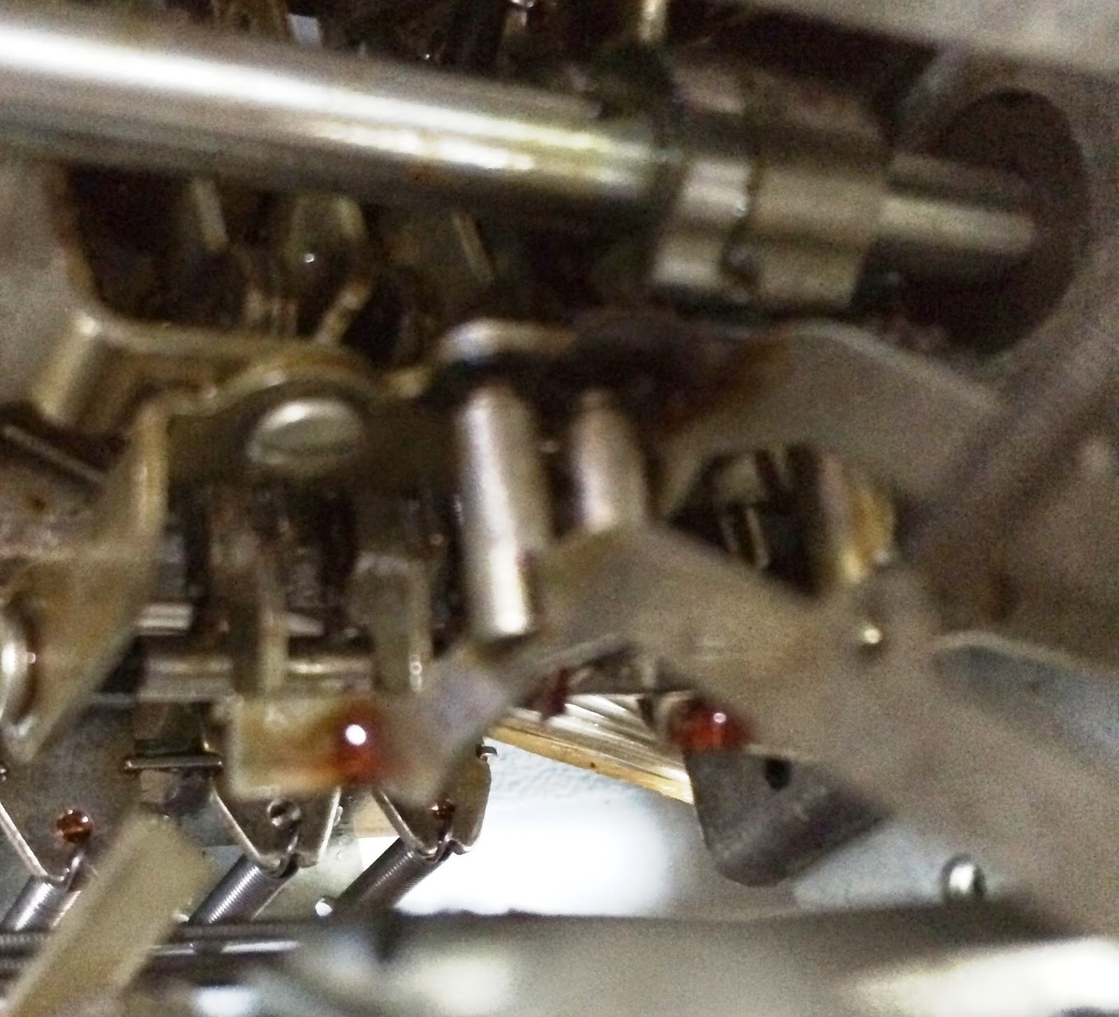
To my surprise, nothing typed. Not so surprising when I took a glance inside the top of the typewriter - the drive belt had broken. I was afraid that the rubber had dried too much for these belts to be trustworthy, and my fears were proven out. Why, however, did it have to happen immediately after I put everything together and checked this peripheral off as restored? Grrrrrrrrr.

Broken motor belt atop the newly reassembled console printer

1131 MEMORY CARD DIAGNOSIS AND REPAIR

I removed the card at gate D, compartment A1, slot M3, which is the address driver card which was faulty for addresses of the form '01100xxxxxxxxxxx', in  order to repair it if possible. I have a testbed to mount SLT cards, supply the three voltages they need, and to check out why the card is failing.

If the fault is in the discrete components on the card, a repair is fairly easy. I am hoping that it is a failed transistor, which has readily attainable substitutes that can be soldered into place. If it is one of the diodes or other parts inside an SLT module, the aluminum covered square modules on the card, it may be harder and more cumbersome to repair the card.

The card has eight IBM 131 discrete transistors, two 361457 modules (FTX - four 9V transistors) and two 361456 modules (AOXb - and-or-extenders), plus a multiresistor pack, a multicapacitor pack and one filter cap for the 8.3V. I am working out the wiring for this, between the general schematic in the memory ALD, the pin assignments and the card itself where I can trace out some of the connections.

Testbed to begin diagnosing the fault in the 5803467 card
A superficial examination shows all pins have good connectivity and all transistors appear to be working. The card only receives +6V for the address selection use, 8.3V for the FTX module and discrete transistors, and ground. No +3 or -3V supply is consumed on the card and the use of +6 is quite low, simply to bias the diodes of the AND function for the address selection.

I then checked the resistor and diodes of the address selection logic, which were all good. The card requires more than the usual SLT voltage levels and driving, which is why I didn't yet try to power the card and watch it operate. There is the 8.3V level for one part of the card, but it also requires a current source to feed the other half - it implements both the read driver and write gate circuit. I suspected it would take a bit of design and fiddling to get all the drivers and sinks. The 8.3V is trivial but not sufficient.

I next did some in-circuit testing of the transistors and diodes. They all operated as diodes with the correct voltage drop - treating the transistor as a pair of diodes sharing one terminal. However, when I tested the transistors as three lead devices - which gave me good results on seven of the discrete transistors but one of them was not altering the collector current as the base current changed. It was still just a pair of back to back diodes with a center wire. I had found my bad part!

It was totally consistent with the symptoms - this transistor was for addresses with bits 3, 4 and 5 of '100' which is where the problem manifested. It is marked as a Texas Instruments unit but numbered with IBM's house values - 131. I looked up some handy substitution charts that gave me a replacement type of 2N2696. This PNP transistor is not in current production but there are a few on eBay. However, it was a close enough match to NTE159 and therefore to the very common 2N3906 part.

I had some 2N3906 on hand and carefully removed the IBM transistor. Because the leads are soldered on both sides of the SLT card, removal of the leads and replacement through the cleaned out holes would take more heat and time than I wanted to apply to the card. It has thin traces linking those pads to other parts of the circuit, which might be damaged by excessive heat.

I therefore clipped the transistor off close to the can. leaving the three leads attached to the board. I formed up the new transistor to solder onto those leads and sit low enough to fit inside the card compartment without touching the adjacent SLT card. I soldered it in place, tested everything and then inserted the newly fixed card into the A1 compartment, slot M3.

Replaced transistor on repaired memory driver card (5803467)
I powered up the 1131, tested the formerly bad address range which now worked normally. I used the Storage Load and Storage Display functions (CE Switches hidden under the cover near the usage meter) to load and then check various bit patterns throughout all 16K words of memory. Flawless operation now!

NEW KEYPUNCH INTERFACE DEVELOPMENT

I began further testing with the keypunch interface and found that although everything was working well initially, after doing reads, an attempted punch hung up and after this the keypunch was again refusing to recognize a card registered in the punch station. I need to understand this in order to make appropriate adjustments.

It didn't appear that I had any connections which could feed back into the keypunch. All the punch, space and other key/switch activations are done with relays, which remain open when dropped. I sense the state of the registration relay by a reed switch, thus I am uncoupled from any circuitry.

The only direct link to wiring is the set of read contacts at the dup station and the +5V I inject to the common plate to read the signals. It may be that there is a path I don't recognize from those, which should be totally isolated by the DUP relays as they sit in their dropped state. Further, when they pick, the disconnect all my wires.

If I have an error where I leave some of my control relays picked, it could cause a problem but I don't see any indicator lights inside the interface box which would glow when I am picking any of the sixteen relays.

I am going to do some studying of the circuits in the keypunch to see what could possibly be happening here.  In the meantime I decided to work on the memory card - results reported above.

Saturday, October 25, 2014

Console printer working correctly, plus minor work on keypunch interface and card reader

1053 CONSOLE PRINTER RESTORATION

I worked the various levers, pawls and other parts of the carrier that are involved in escapement (spacing) and tab operations. As part of my investigation I noticed a crack in the carrier string pulley on the right side that maintains tension on the cord. To remove this as a cause, I replaced the part; no change in the behavior but better to have a good part in place.
Part with crack in white part, front left

replacement part that I installed
Interestingly, the mis-spacing occurs in the same spots, which implies some friction, bent parts or residue in the racks into which the pawls engage. I don't expect to find bent rods, but perhaps there is sludge on surfaces I can't see that are impeding the operation. If I hand-cycle the typewriter after pushing the space button, at the columns where I have problems, I can see it either fail to move at all or move half a column.

The half-column movement can be caused by the backspace pawl and escapement pawl being out of adjustment, so that it sometimes stops at the backspace rack tooth (half-column). I originally attributed this to sludge between the pawls which slide over each other and around any pivot arms. I have worked so much lubricant through this area that I am losing faith with the sludge hypothesis.

Another failure mode, also occurring in the same area of the machinery, is the failure of a tab operation to latch, which is necessary so it can slide rightward until a tab set tooth releases the latch. It is bouncing but not latching, resulting in a skip of a few columns - but not tab set exists at these locations.

Later today I worked the pawls some more, ensuring they all slid easily and independently. Now, with power applied, the spacing and tabbing seem very consistent. So good that I am going to close up the typewriter cover and consider this restored. Patience paid off.

1442 CARD READER/PUNCH RESTORATION

The cornering station and ability of the stacker feed rollers to take the card away remain a problem. I did more cleaning, tweaking and attempted to adjust the pressure rollers for those stacker rollers. So far, it is no better. I was able to boot the cold start card from the reader and it appeared to be correct in core. There is a check condition at the end of the read but if the data got in correctly, I have to assume the problem concerns slowness in the card movement due to residual sludge. With patience, this will be corrected just as with the console typewriter.

NEW KEYPUNCH INTERFACE DEVELOPMENT

With the interface cabled into place, the keypunch is being cantankerous about recognizing a registered card, sometimes leaving the keyboard locked so I can't punch on the card. Removing the cables restores the keypunch to normal operation, which means the cause is something happening within my interface box.

Friday, October 24, 2014

Bits and pieces on other tasks plus strong progress on new keypunch interface

NEW KEYPUNCH INTERFACE DEVELOPMENT

The mysterious reset of the Arduino when I punch columns was traced down to a loose power connector, as I thought it might. I could punch characters well but not spaces. I found that I was firing the space magnet for the original 10ms duration while the punch magnets are fired for 20ms. Once I extended the space magnet to the same 20ms operating time, I could punch cards in ASCII at will.

My binary mode error checking is still a bit touchy, something I have to work on tonight. I could get some binary mode punching to occur but when I tried the automatic multipunching, I found a flaw in my logic. That too will be fixed up tonight.

I tried to read a card next. Although the machine did space a full card width, my logic was always picking up spaces regardless of the holes in the card. I made some adjustments to the reading routine, but there is the chance that I will need to alter the time when I latch in the state of the read station contacts.

There is an issue I have to resolve with my 029 keypunch itself - cards that move into the read station area are not being pulled into registration by the pinch roller, nor do the cards get pushed by the other pinch roller so they are not far enough in the stacker area to be pulled up well.

After cleaning up the problems in my Arduino code and doing quite a bit of testing of the error checking, I took the unit out and attached it to the keypunch again. The results were puzzling - odd punching results, lack of spacing during the read command, and then a continual failure to recognize that a card was registered at the punch station.

It is late and I will resume testing tomorrow - I wonder if the attachment of the cable is incomplete or if there is something very subtle that broke? Anyway, careful testing will lead me to the problem.

1053 CONSOLE PRINTER RESTORATION

I exercised the mechanism some more, improving the spacing a bit but it is still not working smoothly enough or consistently enough - this will take patience.

1131 DISK DRIVE RESTORATION

I turned on the drive with a good cartridge and worked on some seek operations. Everything checked out okay. I attempted to cold start DMS2 from disk but the card reader wasn't quite healthy enough to get the whole boot card into core correctly.

1442 CARD READER/PUNCH RESTORATION

I tried booting a diagnostic card through the reader with apparent success, but when I moved on to try a DMS2 cold start card, check conditions resulted in an incomplete read. The reader is still suffering from lingering sludge in the mechanism.

EMULATED IBM CHANNEL PROJECT

I found pinout diagrams for the cable I own and for the card I have. It appears the cable assembly I bought is for use with the Block Multiplexer Channel card, which lets a PC connect to a mainframe channel and the PC seems to be a device. The card I own, the Channel Emulator/A, appears to be a mainframe channel and can attach to real devices which think the PC is a mainframe.

The connectors are different between the two card types, thus I need an adapter to convert my card to my cable. Now I have the ability to design the adapter because I have the two diagrams, indicating which channel signal is assigned to which pin. 

Thursday, October 23, 2014

Interface testing, some adjustments and improvements, but not yet done

NEW KEYPUNCH INTERFACE DEVELOPMENT

It was another heavy work day but I did get a few hours in the shop tonight continuing to test and refine the keypunch interface. One of the issues I uncovered is embarrassing to admit. The reader cable is hooked to a mechanism that reads the holes in a column of one card in order to duplicate the holes in the following card sitting at the punch station. I will use it to read cards and to verify that a card matches what we punched one cycle before when it was going through the punch station.

The contacts that will be made when a hole is present close a circuit to deliver 5V back to the Arduino, but this only happens during an escapement cycle (moving from one column to the next). When the card is not moving the contacts are open. Connecting the contacts to the Arduino, whose input pins are in a high impedance state, means that we don't have a reliable signal from that input except for the contacts at the moment they are recording a hole. The contacts recording an unpunched location remains floating.

The right thing to have done, which I had to retrofit to my interface, was to pull the Arduino pins down to ground through a 10K resistor, which causes the inputs to sit at logical 0 except for when a contact is closed through a hole, pulling that input up to a logical 1 state. It is a big clunky, having to be done by splicing wiring between the reader cable and the Arduino to hook up a resistor, with the common terminus of all twelve resistors hooked to ground.

During my testing, trying to drive the keypunch, I was having to deal with the three cables loosening or pulling off the interface. This is because the cable ends inside the keypunch are not very long, requiring the interface box to hang down near the relay panel of the keypunch. The serial cable I am using to test is short as well, barely reaching up to the table of the keypunch where a small Surface Pro tablet provides a terminal that I can use for testing. The motion of the keypunch mechanism and the precarious hanging position of the box caused many cable disconnects or flaky connections.

I spent about an hour working on the mechanical aspects of the interface, particularly the two DB25 and one DB9 connectors, to allow me to securely screw down the cables that attach to it. With that done, I could restart my testing.

I found right away that it would trigger a punch just fine with the 10 millisecond pulse I originally designed in to the program, but something goes wrong that causes the Arduino to reboot after it punches one column. It may be a vibration issue or a loose power connection - I ran out of time to explore the cause - but there is definite progress and some confirmation that the interface will eventually work satisfactorily.

It is now late and I am too tired to keep flogging away at the testing. Tomorrow and the weekend is when I will get back to this task.


MAINFRAME CHANNEL EMULATOR CARD

I have an IBM emulator card that was used with their PC based mainframe offerings - XT/370, P/390 etc - which would let me communicate with any bus/tag based peripheral. In addition to the card, I have a cable which has bus and tag connectors on two ends and a third end that plugs into an IBM emulator card. To make this work, it has to be put into a working PC and it needs the driver software.

I don't have the driver software, but a friend does have it and is willing to sell the disk to me. There is a better than even chance that it won't work, since there are a few versions of the IBM channel emulator card, each with its own version of the software. I already know I have another challenge, because the cable set I have uses a connector with four rows of twenty pins, but the emulator card has a longer and thinner connector with only three rows of pins (but more pins on each row).  If I can figure out what the three row connector assigned for each bus and tag signal wire, I can make an adapter. However no guarantees.

Then of course I need to set up an old IBM PC with a microchannel bus, which is the bus type of the emulator card, which brings some additional complications I am sure. I don't have a current device that needs a bus and tag connector, but it will be a handy testbed to support any peripherals I might get in the future. More of a speculative activity than most of the tasks I am undertaking, so this will sit at bottom priority and may take quite a while to be finished.

Wednesday, October 22, 2014

Testing new keypunch interface with IBM 029

NEW KEYPUNCH INTERFACE DEVELOPMENT

I checked the behavior of the punch cable lines against expectations, prior to hooking up my interface box. Everything worked as expected except for pin 20, which was intended to be a 48V supply for the Release relay. It was not delivering power, which was a result of an inappropriate choice of SMS connector pin for the wire. I found a better pin, A08-E, and hooked to it. Now everything on the punch cable works properly.

I then checked the behavior of the read cable, although I didn't address the timing of when a column's holes are detected. I did see the power blip up whenever the chosen row had a hole. There is a hardware change I need to make to the interface box, to add 10K pulldown resistors.

Otherwise, the signals from the dup (reader) station float at high impedance when not powered due to a hole. On the Arduino, the detected logic level is indeterminate during the high impedance time, not a logical zero which we want. The pull down resistors will fix this.

I will solder the resistors into the box tomorrow, but want to do some testing today on the remaining functions. I hooked up the box and a terminal program to the serial port and ran it through some paces.

It is correctly detecting cable presence, card registration in the punch station and other status, plus correctly triggering release and clear switch actions. What it is not doing is punching - the relays are not energized long enough to fire the keypunch. I know that hand connection of the pins will fire off spacing and punches, but that is much longer than the 10ms that was used on the original interface.

I adjusted the duration to 20ms and will dial it up further if that isn't long enough to trigger a punch cycle. I expect this may be enough because the release key works properly, the difference in activation is 15ms duration for release and only 10ms for the other punches, plus the common power for the punches is interrupted by a cam while the release key is not.

At 20ms, the keypunch did exactly the same thing - nothing. If I didn't trigger spacing and punches by a jumper across the cable, which is what the relays do when they activate, I would think I didn't have the proper common power source. Since that was what worked with the jumper, and since I can hear my relays firing while the keypunch does nothing, I will ramp up the duration once again and see what happens.

Looking at the schematics, it appears that interposer bail contacts are the connection that fires off the punch and escape solenoids, however if that is true I don't understand how my jumper could cause punching and spacing nor how the original interface worked successfully. I need to do a bit more research on this.


Monday, October 20, 2014

New keypunch interface controller box tested extensively, ready to connect the 029 keypunch for final testing

It was a busy work day and tomorrow will be even more jam packed, but I did get some time to test the keypunch interface box.

NEW KEYPUNCH INTERFACE DEVELOPMENT

I added in support for XON/XOFF flow control in a way that will protect us from deadly embrace problems and fits in cleanly with the logic flow. When we detect an XOFF from the user side, we flag the occurrence and will not pass along completed commands to be parsed and processed. We won't be sending any data to the user during the accumulation of a command line, thus won't overflow their buffers.  On our side, we are vulnerable to buffer overflow during the long duration activities when we are operating the keypunch, so we will send an XOFF at the start of command execution and XON at the end.

If the user terminal sends an XOFF to us in the middle of a command, when we are sending text with status responses or a card image in the case of a read, we might overflow the user terminal. To fix this would require us to write into a buffer and have a separate process emptying it subject to flow control. The impact of losing part of a status message is low, so we will accept this risk.

The card reading routine, however, could overrun the users receive buffer because of the 89 or 409 characters we will send as a single action before completing the read command. The Serial1.print() call will block until it can pump the last of the data into the 64 byte output buffer, which means we can't read the incoming serial stream to spot an XOFF.

If we could peek at the incoming serial buffer to spot an XOFF, we still wouldn't be able to stop the output in time. The Serial library in Arduino has no flow control - it will just pump out bytes until the buffer is empty. In order to guarantee successful flow control, we would have to institute a separate buffer for outgoing messages and pump it out by some method that would be given control in spurts to send out just enough to fit in the output buffer. Peeking at the receive buffer is also a challenge because the Arduino environment only gives us the immediate next character, not any behind it.

The user serial link issue was resolved - wire snapped in a harness inside my interface. I continued to debug code and clean up behavior. The relays appear to be operating correctly except for the row 12 punch relay which makes no sound. I will check that wiring. In addition, some of the relays sound but the signal LED on the relay board doesn't illuminate. Not sure if that is significant or just a flaw in the board. I will do some connectivity testing of the relay contacts before hooking up my keypunch cables.

After a bit of double checking, I discovered that one of the pin assignments was incorrect and that two signals were assigned to the same relay leaving the other relay disconnected. After making quick changes, I retested and everything clicked and lit as it should. Next up was a test of the DB25 cable connections to ensure that I am controlling each wire I expect inside the keypunch.

Everything checks out for the connections that are switched through the 16 relays. I also checked the pair of wires in each cable which are shorted to allow the Arduino to detect if the cable is connected or not. Finally, I tested the pair of contacts that hook to the reed switch detecting when a card is registered at the punch station.

The only part not tested is the reader cable which will detect the presence of holes in cards as they are moved through the dup (reader) station. Once I do a quick sanity check of the wiring in the keypunch, I will plug in my cables and run the diagnostics.

Sunday, October 19, 2014

1053 debugging, SAC interface circuit testing and good progress on keypunch interface controller

1053 CONSOLE PRINTER RESTORATION

I hoisted the console printer up for access to the contacts and began to check continuity and operation of all the contact/switch units on the typewriter frame. Amazingly, given all the oxidized contacts in the rest of the machine and peripherals, everything in the 1053 worked properly.

Checking switches and contacts in the 1053
The erratic spacing has to be mechanical, therefore. I did some spacing with the hand crank wheel rotating very slowly to see the operation at the moment of release. I saw spots where the carrier did not move forward at the release, while in most spots it jumped promptly to the right.

While it could be a bit of sludge on the escapement and backspace rack teeth at the failing spots, I am still leaning to residual sludge between the escapement, backspace and tab levers keeping them from snapping back in place as they should under their spring tension.

I know that the tab should latch the escapement and backspace pawls out of the way until the carrier runs into a tab lever in some column that is set, which releases that latch. On some tab operations, however, I see the tab lever fail to latch so that it moves only a few columns over.

Since the latch is part of the stack of levers along with escapement and backspace, it reinforces the theory that it is sludge in the levers causing all these problems. Access is difficult without disassembling many parts that must be carefully adjusted upon reassembly.

Stack of tab, backspace and escapement levers, looking at tab lever on topo

Escapement and backspace rack teeth visible toward top, bottom pins are the tab stops

Another view of the stack of levers where I suspect sludge is causing problems

NEW KEYPUNCH INTERFACE DEVELOPMENT

I deferred debugging the problem with the user serial link, due in part to the total ambiguity surrounding PC serial port links -

  • DCE/DTE
  • which of dozens of permutations of control lines are used (CTS/RTS/DSR/DTR. . .)
  • voltage (TTL versus true RS232)
  • cables (all wires, partial wires, straight thru, crossover, control signal loopbacks)
  • NL, CR+NL (a terminal program variation rather than link per se
Instead of attacking the link, I temporarily changed the input routine to use the USB serial0 link associated with the Arduino code upload. With that in place I could do quite a bit of testing of my logic. In some cases, I added temporary 'Serial.print' instrumentation.

 I have worked through quite a bit of the functionality successfully, other than the question of whether it does what I expect to the keypunch. Identified issues to debug are:
  • Punch command with more than 80 columns of data is not detected and truncated
  • Verify mode doesn't properly handle shorter card for punching than prior card being checked
  • Serial1 link is not working, no output displayed by my terminal program

There is still more to check, such as:

  • translation under binary and user table mode
  • proper loading of the user table, 
  • parsing of binary mode punch commands
  • verify operation correctness
  • keypunch function timing 
I put together a pigtail power connector to hook to the Arduino from the main 12V power brick, since it is powered by the USB cable at the present, but no USB cable will be in place when the interface is in normal operation.

One part of the spec is not implemented - XON/XOFF flow control - but that shouldn't be hard to add in as testing wraps up. No point worrying about it until I get the user serial link working.

Later in the evening, I worked on the code and resolved all the known errors except for the serial link which I am avoiding for now. I also tested the binary translation mode, entering punch data in binary, and related functions. Ignoring the serial link issue, the rest of the testing should be done hooked to the keypunch.

SAC INTERFACE FOR ADDING PERIPHERALS TO THE 1130

Initial issue when I began testing my SAC interface sample circuits, but it turns out I mis-selected all of the transistors. All I had on hand were some IBM 077 and a random NPN small signal transistor, not the parts I had simulated. The failing circuit was the driver which takes a TTL input and drives an SLT transmission line as output.

I will do some simulation with varying part characteristics later tonight, even though I plan to replace the current transistors with the part number I will use for full scale production. If I find tweaks that make it less sensitive to component specs, I will apply them. 

Saturday, October 18, 2014

Disk drive timer finished and installed, SAC interface circuits built, and debugging underway of the keypunch interface

1131 DISK DRIVE RESTORATION

I finished assembling the timer neatly into a plastic project box, with appropriate air holes to dissipate  the heat produced by the zener diodes, voltage regulator and relay timer board. One final test validated correct operation - roughly 105 seconds after the motor is switched on, the heads load when the timer circuit activates. It is now installed and the disk drive enclosure put together.

Timer circuit in its enclosure

Timer box in its final location

Everything closed up, front door in place

NEW KEYPUNCH INTERFACE DEVELOPMENT

When I retrieved my power brick and powered the Arduino, it showed some pathology without being hooked to anything. Periodically, the Arduino would reset and start over, which I suspect is a power protection reset due to excessive draw by two relay boards fed from the Arduino.

I think I can take the 5V from the brick input and bypass the rest of the Arduino circuitry that is overloaded, although I might need to add my own 5V regulator on the power if I see any signs of sensitivity to power variations. I have to sort his out, but by removing the connection of +5 from Arduino to the relays and connectors, I can resume testing some logic for now.

I cleaned up code for quite a while with the 5V disconnected, but when I tried to open the user serial link to get into more serious debugging, it was clear that the serial port card I use also requires 5V. I had to separate out the connections from those for the power hungry relay boards and connect it individually before I could begin talking to the Arduino.

Next minor snag - the interface box has a male DB9 connector and the only USB-serial adapters I have also have a male DB9 connector. I found a female-female adapter but when I began testing it was clear that it was not a crossover inside. I need to have a crossover adapter or cable with female connectors on both ends.

The power brick for the Arduino is 12V, which is dropped to 5V by an onboard voltage regulator, so I will need to wire up a voltage regulator in order to feed the relay boards bypassing the Arduino onboard power system. I have the parts and began to build it, while ordering the DB9 adapter I need to continue testing.

Discovered that the relay board activates a relay on logic low input, not high. Reversed my logic and all was well. I changed the code controlling the relay signals to use an indirect value - PICK or DROP - rather than LOW and HIGH due to the potential for confusion because of inverted activation.

Set up the voltage regulator and an external 12V 4A power brick. Now that I have the right adapter and power to the system, I am still not seeing output from the user serial port nor getting any input into the system.

SAC INTERFACE FOR ADDING PERIPHERALS TO THE 1130

I breadboarded my receiver and driver designs for the SAC interface, but will postpone testing until tomorrow. I have to set up +3 and +6V power, some TTL driver and receivers, and then wire it into the SAC adapter for testing. I want to move carefully to avoid damaging the 1131. I will pick an interrupt request line as my driven signal and the corresponding int level active line as the received one - an easy pair to test with that don't require any other signals to be connected.

My board has twisted wires, similar to the twisted pair used in the IBM signal cables. My bench power supplies will deliver the SLT voltage levels and a digital trainer unit I have offers TTL level inputs and outputs. When all set up, I should be able to flip a switch, step the 1130 to have it enter an interrupt routine, and see the indicator lamp light reflecting the entry.

Friday, October 17, 2014

Disk drive timer final construction plus initial testing of keypunch interface controller

1131 DISK DRIVE RESTORATION

My new approach was to drop the 48V power, which switches on when the motor is activated, using a sequence of 4.7V 3W Zener diodes. The eight diodes bring the 48-52V down to the right level to feed the 7812 voltage regulator. The timer board activates its relay after 110 seconds, which disconnects the logic signal from ground to indicate it is now safe to load the disk heads.

This worked well in practice, so I began to install it into the system. The old relay is back inside the power box, but my wires take the 48V from those connections out to the new box I built. The plastic box contains a board with the zener diodes, the regulator chip and the timer board, hooked to the four wires I routed out of the power box.

NEW KEYPUNCH INTERFACE DEVELOPMENT

I completed the Arduino code and began testing the unit. The first stage was to validate the basic communications link, startup process and first level diagnostic tests. Once done with that, made more difficult by failures of the Java code in the Arduino workbench which left my serial port unusable until the machine was rebooted. The port that failed is the basic link over the USB cable used to program the board, not the one that users will use for commands and data flow.

I now suspect that the USB port can't drive the power that the Arduino plus its two relay boards are drawing, thus it is going offline periodically. My power supply bricks for the Arduinos are in a side shed which would be inconvenient to look through in the dark.


Thursday, October 16, 2014

A lot of Arduino coding, some hardware prototyping


1131 DISK DRIVE RESTORATION

I received all my parts and began assembling the disk drive delay system that waits 90+ seconds after the platter motor spins before loading the heads. I gave up on trying to shoehorn it all inside the power box in the place that the relay itself had taken, instead placing the circuit into a plastic project box that I can put nearby to the power box but still within the 1131.


I wasn't happy with the performance of my first circuit after some testing. I will try a different approach. I certainly don't want anything that might dump the heads onto the disk surface too early.


NEW KEYPUNCH INTERFACE DEVELOPMENT

I coded the remainder of the Arduino code for the keypunch interface today. While I still believe it would be better to add a signal from the keypunch when it is actually punching, both for validating proper execution and to time the release of the punch relays,

I implemented this with the timing based logic used in the original keypunch interface. For example, the punch relays are held for 10 milliseconds then released, after which I wait another 100 milliseconds for the punch cycle to complete.

I believe that the read pins in the duplicate station are active just after I drop the punch relays, which is how I coded the controller, but I can slide this anywhere in the 110 ms total cycle to ensure I capture the state of the holes at the read station while in the midst of punching at the punch station.

I have a small bit to change in how I handle the binary mode lines, otherwise this is ready to begin testing.

Tuesday, October 14, 2014

Working the last vestiges of sludge out of the gummed up 1053 printer and continuing the software development for the keypunch interface

1053 CONSOLE PRINTER RESTORATION

I cleaned up and applied more grease on the carrier rails, then oiled other parts of the mechanism. It is still erratic and my suspicions are turning to the contacts and micro-switches that inform the adapter when a print operation reaches certain stages. With all the other contacts in the 1130 that had oxidized into permanent off switches, I need to check all the circuits for continuity.

I did notice that the right margin  and end of line detection is a bit erratic. From time to time it doesn't trigger the carrier return or index, just typing to the end of the platen and chattering away in place. This is likely to be sticky old lubricants as well. After some work with oil and exercising joints, it is much better, including a clear bell ring on reaching the right margin, but it still fails to trigger the CR once in a while. More work with lubricants, cleaners and repeatedly hand moving all the moving and sliding parts.

NEW KEYPUNCH INTERFACE DEVELOPMENT

I completed all the command validation code, leaving just the execution of the commands to implement. By early evening, I had about three quarters of the execution logic coded as well. The main part still remaining has to do with when to fire the punch or space relays and when to release them.

I am looking for a means to determine when to drop the punch relays - I could use a fixed time but it would be better to watch something like the cam contacts which operate at fixed points during a punch cycle. I could add a wire to the punch cable, hooked to a reed switch around the escapement relay, which would give me a pulse right at the 180 degree point of a punch cycle just as the card prepares to move to the column that will be punched. However, I am not sure what happens during a multipunch.

Some scoping of the machinery and testing of code is probably necessary to get this to work as intended. I am going to write the final execution code with pseudocode in place of the timing delays or condition tests, allowing me to finalize it once I have done tests with the keypunch.


Monday, October 13, 2014

Console printer responding to 1130 program instructions, plus minor progress on other fronts

1053 CONSOLE PRINTER RESTORATION

While doing my studies on the spacing mechanisms, I came across a diagram giving me adjustment advice for the contact bails that touch the microswitches for carrier return and tab operations. These block issuance of new print commands until the variable duration events (return and tab) have completed. I think they are adjusted properly but I can fine tune this once I am able to run the printer from diagnostic programs and watch on a scope.

Adjustment instructons for contact bails and microswitch levers
I put in several hours seeking the cause of the machine gun space repeat that occurs when I push the space button. The same operational cam restores and stops cycles for backspace and tab, which share the cam. I lubricated and worked every pivot and sliding surface I could find, but still had the problem.

It was hard to track down because it didn't fail when I hand cycled (rotated the mechanism by hand with a wheel crank) slowly, watching all the moving parts. It will sporadically take a few extra cycles if I spin the wheel crank rapidly. Under powered movement, it never stops repeating.

The mechanism is complex, triggered by three different sets of components. The button I push will cause a keylever to move down, just as it would if this Selectric had a keyboard, triggering the interposer to snap back and activate a cycle. When a character is printed by the type mechanism, a shaft rotates a cam that causes a single space to occur. Finally, a solenoid can be activated by program control to trip the interposer, causing a space cycle.

Both the solenoid and the button cause the stuttering perpetual spacing, but the print cycle cam does not. Since this worked when the 1130 was last in service, I thought that the adjustments must be okay. This had to be gummed up lubricant but I believed I had found, oiled and worked free every possible moving point.

Finally, I noticed that sometimes the space keylever was touching the interposer while the other functions had a slight space between their levers and interposers. Looking very closely at the keylever, I saw a small pivot which couples the arc of the keypress motion to the interposer at that contact point. I tried flexing those pivots, which seemed to be working okay.

The keylever with its pivoted actuator lever slides through a notch in a cylindrical stud that aligns its movement. The stud for the space function looked to be bent slightly to the left and downward compared to the others. When I operated the keypress elements separately, I discovered that the actuator was binding or grinding on gritty sludge in the slot, made worse by the bent and twist of the stud.

Keylevers sliding in slot of cylindrical studs, triggering interposers at bottom

Bent, twisted and gummed up slot for the space keylever, before repair
I bent the stud into proper position, lubricated those slots in the studs, scrapped the old crud off the side of the actuator, and tested everything. Voila! It now spaces cleanly without any repeating. Time to put the printer mechanism back onto the 1131, connect the cables and begin testing the operation under processor control.

After hooking it up, I began issuing commands to it from the 1130. It was a touch sticky for the first few characters but then began reliably selecting the proper characters. Interspersing upper and lower case proved out its shifting function, rotating the typeball 180 degrees to select characters from the lower or upper case side.

The red and black ribbon shift commands worked properly, although since I had an all black ribbon installed I couldn't verify that it was typing through the intended half of the ribbon. Spaces and carrier returns worked properly, but not the line feed, tab or backspace operations, initially

After a bit more work with the printer, it was typing every character correctly in both cases and executing all the functions. Sometimes, the line feed (index) operation would stick on, which tells me I have a bit more oiling and cleaning to do in that area.

Printing character pair at full speed to test spacing accuracy
The main issue is irregularity of the escapement, both spacing and backspacing. I ran a diagnostic routine to drive the printer as fast as it could go, Over time, the spacing got better but still not perfect. I have some more cleaning and lube work to do until the escapement operates flawlessly. I have a short video showing it operating under the short diagnostic routine, alternating two characters that really show spacing irregularities.

Video of console printer while exercising the print escapement

1131 DISK DRIVE RESTORATION

I decided to use an LM7812 voltage regulator chip on a heat sink to drop the 48V from the disk drive down to the 12V used by the time delay board. This will pull 1.25W while timing and 2.5W while the drive is running. The parts are ordered and should be here midweek.

NEW KEYPUNCH INTERFACE DEVELOPMENT

I completed more of the parsing and verification code that will run in the Arduino. Overall the code is about 20% complete but soon will be sufficient to begin testing in parallel with further development.

Sunday, October 12, 2014

More progress restoring the 1053 console printer, plus continued coding of keypunch interface

1053 CONSOLE PRINTER RESTORATION

After studying the mechanisms last night, I was armed with a good understanding of the parts involved in triggering and resetting the index cycle. I went out to the printer, discovered the errant pivot and freed it up. I ran the machine with power on, watching it cleanly execute carrier return and index operations exactly once.

The next issue is lack of activation of the second operational cam, which drives space, backspace and tab actions. When I activate the interposer links for space or tab, the cam is not activating and turning. I took the time for a bit more studying, to understand all the moving parts involved with this activity, before freeing it up.

There is a plate that rotates relative to the operational cam, either pivoting a pawl into the ratchet when moving the cam or retracting it when the cycle is done. This was so gummed up that it wasn't moving, but I worked the old lubrication out and got it moving. At first, it would latch but not release, until it was free enough to work reliably both ways.

Next, I found the escapement which controls spacing and backspacing was not working smoothly. It seemed that the pivot mechanism for the escapement and backspace pawls has those pawls slide left and right as well as rotate, but due to a gummy film between the layers, they were not sliding back and forth. Some attention to that cleared up the problem giving me a crisp spacing action.

Tab works smoothly as well. The problem is that the three actions driven by the left operational cam, space, backspace and tab, are can stick on taking repetitive cycles. The fault has to be in the restoring mechanism, guiding me to the next spot for special attention.

I also found a writeup in the theory of operations, sans any diagrams, that explains a bit about those bails for the operational cams which were configured two different ways. Based on the writeup, I should be able to sort out which is wrong and correct things. These are meant to block re-triggering, so the left one could be causing my problem with the tab, space and backspace.

The left operational cam is still repeating cycles. When I hand cycle the machine slowly it almost always rests properly. Hand cycling rapidly will sometimes give a few cycles before resetting, other times it resets correctly after just one cycle. Under power, however, it never resets, striding across to the right with continuous spacing or continuous tabbing or racing backwards in continuous backspaces.

I will keep at this until I find the sticky pivot and free it up. I had triggered some character cycles which seem to work properly, although I didn't have the platen installed or paper and ribbon in the machine. If I can get the operational cam restoring well I should be in position to start testing printing and then reinstall this in the 1130.

After more work, the tab and backspace take just one cycle, as they should, but the space function continues to be pesky. Under motor power, it never stops, taking constant cycles until I pull the plug, but when I cycle it slowly the clutch works properly. I will look into the adjustments for the restore, although it seems that this machine was working properly when retired so its adjustments should be correct.

NEW KEYPUNCH INTERFACE DEVELOPMENT

I structured the program module with separate tabs for each major module and began more detailed coding. I completed the function which extracts a command line from the input serial port stream, then moved on to coding the parsing routine that breaks apart and validates the command line.

I did discover one flaw in my protocol, which is built around a line of no more than 81 characters, but has a command to load a user translation table requiring 516 characters. I had to modify the protocol to handle this given a max of 81 characters per command. The _LOAD command now handles one position of the translation table per line, specifying a decimal value for the character to be updated and then four hex digits as the keypunch actions for that position.

Saturday, October 11, 2014

1053 console printer restoration work, plus more coding on keypunch interface

1053 CONSOLE PRINTER RESTORATION

The cause of the perpetual print cycles was a small spring for the restoring lever, underneath the machine, which had come loose when I connected the cycle latch lever spring a few days ago. After putting it back in place, the machine does not attempt print cycles when not requested.

Hand cycle wheel in place - apologies for the blurry focus

Spring hook tool used to affix small springs
I used the Hooverometer, an IBM tool for making certain settings on these typewriters, to get the cycle clutch latch lever set properly, since I had removed it to move my new motor belt into place. Setting up the tool to marker 3, it is placed on the latch pivot pin and the hook should just touch a shaft above. Moving the cycle clutch latch until these lined up properly and tightening down the screws was all that had to be done.

Hooverometer in approximate position for cycle latch adjustment

Hooverometer tool for adjusting Selectric typewriters
Index (line feed) operations keep occurring because the interposer (part of the actuating linkage) isn't returning to its full forward position after an index cycle is taken. A restore bail should be accomplishing this. So far, I have looked to verify that no springs are missing and moved the various parts of the linkage to ensure they are not gummed up.

In spite of this, it is still not restoring and thus taking perpetual index cycles. I will need to investigate this further, after I spend quite a while poring over the theory of operations, adjustments and illustrated parts manuals.

I adjusted the red ribbon shift tape tension to get the new replacement tape I installed working correctly. Nothing in any of the manuals advises on tape tension or setup. You loop the tape around and then have to guess how much to move the right hand tape pulley in order to have black or red print depending on the selection.

Right pulley with plastic ribbon color shift tape, adjustment screw at right

Armature to pull or release the ribbon color shift tape 
I tightened the tape while watching the ribbon lift cam follower latch plate shift to the front, however the tape snapped off the metal clip on the right end. Sigh. I was able to improvise a way to hook the clip back on, loosened the pulley greatly, and reinstalled the tape. I will err on the side of looseness, which might mean that it never shifts to the red color, but that can be gradually adjusted when the machine is working until I get the proper color reliably.

Tape snapped off the metal clip

Clip pushed through doubled section of tape, makeshift repair
It appears I have the ribbon color shift adjusted correctly with appropriate tension on the plastic tape, subject only to a full power confirmation once I am ready to be printing output with the 1053.

Cam follower latch in its leftward (black color) position
Cam follower latch in its rightward (red ribbon color) position
I will read more tonight on the index actuating and restore mechanisms until I can spot what is not working properly, causing repeated index cycles. The likely suspect is solidified lubrication but it must be at some attachment or pivot point I haven't yet found. The area where these linkages sit is very crowded with other linkages and parts, limiting visibility.

The two solenoids that activate the carrier return and index functions have microswitches that detect the state of the operation, with long leafs on the switches that extend out and can be touched by metal bars on the actuator arms (they are called contact bails).

Carrier Return microswitch with leaf below bail
Index microswitch with leaf above its contact bail
However, the left and right switches are in very different configurations - one sits above the contact bail, the other is below the bail. Once must be in the wrong position. Nothing in the three manuals clarifies which way these should be configured, nor are the diagrams of pictures of the assembly. I need to do more research on this before fixing whichever is wrong.

NEW KEYPUNCH INTERFACE DEVELOPMENT

I retrieved all my design notes from the workspace and began to properly assign all the signals to the Arduino pins. From there, I resumed writing the startup code to initialize the interface. The punch and the reader cables each have a pair of wires connected together, allowing the Arduino to do a quick verification that the respective cable is attached. If the reader cable is not installed, the unit will still work as a punch but cannot read cards or verify during punching.

The USB serial port is used for diagnostic messages - both normal status and errors - in addition to the text responses on Serial port 1 - the user interface - to every command issued on that port.

Friday, October 10, 2014

Short day but some accomplishments with 1053 restoration

1053 CONSOLE PRINTER - SELECTRIC - RESTORATION

I worked the broken end of the old hand cycle tool out of the cycle shaft, then threaded on my newly acquired hand cycle wheel with the degree markings. I used one spring hook I had from an ebay auction to clear out the hole into which the cycle clutch latch spring fits. Now it is just a matter of hooking the spring through that hole deep in the mechanism, then pulling the other end out and affixing it to the cycle clutch lever.

I still have one or more of the pivots, arms, latches or other parts involved in tab operation bound up with congealed lubricant, because when I crank the carrier moves smoothly forward at a fast pace. I will carefully work through the entire chain of parts involved in this, exercising them to free up motion, until the tab operation stops.

As soon as my full set of spring hooks and other tools arrived, I used them to deal with that spring that needed reattachment. These will also help me with the IO selectric mechanism I got from the Itel/Dura word processor - which when restored can operate as a 2741 substitute to deliver an improved 1130 APL operation.

The tab operation was ended by working out the lube, but the unit is currently taking continual print cycles although without a tilt or rotation to a specific character. This may be an adjustment problem since I had removed and reattached part of the cycle clutch mechanism.


OTHER ACTIVITIES

My return from the business trip was quite a bit longer than expected, due to delayed flights, missed connections and extra connections that got me home after 2AM, with a full day of calls booked starting at 8AM later that day. Between lack of sleep, a cold I caught and limited time, I didn't get anything beyond the 1053 work done.

Tomorrow I will spend the morning at the Computer History Museum bringing up the two 1401 machines for an education program and a public demo, since they were short handed. By the afternoon I should be back to the machine, making progress on several fronts.


Thursday, October 9, 2014

Design work on new keypunch interface and on the interface of peripherals through the 1131 SAC

KEYPUNCH INTERFACE UNIT DEVELOPMENT

I began coding the Keypunch Interface code, although hampered because I didn't have the documentation of the pins I wired to the various signals. It did give me a chance to work out a draft protocol for users of the interface. Design objectives included the use of straightforward ASCII messages that would allow people using terminal programs to operate and test the interface.

With the lack of frames or other demarcations in a serial stream, the protocol had to allow unambiguous recognition of each message or command. Further, we didn't want to use any characters or codes that weren't sure to be available with any terminal program or connection. Marking the start and/or end of a message using only commonly available characters means that we can have that delimiter character also appear as valid data within a message. Thus, we needed a means to 'escape' the delimiter, blocking its special role to frame messages.

I was guided by the conversion table already in use at Computer History Museum to punch hollerith coded BCD characters. Since the 1401 encoding uses fewer characters than seven bit ASCII, only a subset of ASCII characters are in the table. I had the unused characters to choose among.

I somewhat arbitrarily selected the underscore ( _ ) to be the indicator of the start of a message. It would also be the escape character to use when the underscore is valid data - pairs of _ in a row are interpreted as a single data value of _ while an unmatched underscore is the start of a message.

Messages begin with _ and have a 'verb' immediately after the underscore. The message ends with the next unpaired underscore. The interface will detect error conditions such as a card punch message which has more than 80 columns of card data before the next message is recognized.

Some of the verbs are session or control functions, while others are used to punch each card or read another card. _P is followed by up to 80 columns of data and a newline to release the card. _R has no required additional content and will return the content of the next card to move through the 'dup' station of the keypunch.

The format of the data being punched or written is determined by a session state, the mode, which is changed by the verb _MODE and one of the choices ASCII, BINARY or USERTABLE. We have defined a standard or default correspondence between ASCII and Hollerith code. The binary mode we defined sends sets of four ASCII characters representing hexadecimal values, where three of the hex characters cover the twelve rows in which we can place a punch while the first or high order hex value supports release and other control characters. The user table is defined to encode a set of the twelve holes for each of the 128 valid ASCII characters.

_LOAD followed by 512 characters which are valid hex values will load the user table. Each group of four hex characters is used to determine the holes to punch or keypunch functions to actuate for a specific ASCII character. The first group of four encodes character 000 and the last group encodes character 128 (decimal).

When punching cards in the binary mode, if the characters sent are not 0-9 or a-f, a valid hexadecimal digit, an error is detected. Similarly, during the loading of the user table, any character that is not a valid hex digit will trigger an error. Finally, our default ASCII encoding will flag an error for any character that does not have a translation to a set of holes - the first of the four hex digits in the table has a value that indicates the character is an invalid character to punch.

If a newline ASCII character is in the stream of characters being punched, or the user table entry or four hex digits in binary mode specific a release, the release key of the keypunch is activated to feed the next card in position to punch a new card. It is a way of speeding up punching of cards once all the remaining columns of the card will contain blanks.

The verb _VERIFY has either ON or OFF as a valid operand. It determines whether the keypunch interface will save each punched card image and verify it when that card moves through the 'dup' station as the following card is being punched.

The interface will automatically detect when more than three holes are to be punched in one column, using the multipunch key function of the keypunch to ensure that no more than three rows are punched at any time, continuing until all the intended holes have been perforated.

The verb _CLEAR with no required additional text will activate the clear switch on the keypunch to eject all the cards in the various stations. Typically this would be done to end a punch job.

The _R read verb will space the card in the punch station which causes the preceding card to move through the 'dup' station and be sensed in the same columns. As a necessity, any deck of cards to be read must have an extra card at the end which is not read but will be used to drive reading the final data card.

The verb_R to read a card must space 80 times to pass all the columns through the sense station, Thus, when verifying with _VERIFY ON, we must be able to sense up to the last non-blank column of the card in the 'dup' station, even if the card simultaneously being punched has fewer columns and issued a release. We punch characters or spaces up to the larger of the nonblank length of the prior card or the content of the current card, to ensure that both punching and reading for verification act on all required columns.

The serial stream is 9600 baud, 8 bit, no parity, one stop bit, wired in DCE mode, full duplex and uses XON/XOFF for flow control. Note that this excludes the use of the ASCII characters XON and XOFF in any user table. Attempting to load those two positions of the table with any value except a special 'ignore' code will trigger an error.

The interface will respond with ASCII text messages to every command - both errors and a clear confirmation of the verb it received and the action undertaken. For the _R read verb, the content of the card is returned in ASCII, eighty columns terminated with a new line, when the mode is ASCII. For the user table or binary modes, 320 hex digits are returned as groups of four separated by a space, ending with an new line.

IO DEVICE INTERFACE TO 1130 USING SAC

As  I continued to build out the logic design for the multiplexing interface to the storage access channel, I found myself with two directions I can take for handling interrupt requests from my attached devices. I can enforce prioritization or I can push some of the control over priority to the software for the various devices and interrupt subroutines.

I can gate the requests and the recognition of XIO Sense ILSW commands to ensure that the higher priority device on my multiplexer triggers interrupts and is serviced first by software. If more than one device on a level has conditions that request an interrupt, I would effectively poll those devices in priority sequence, selecting the top device which had a request.

Only that device's signals would be gated to the SAC. It would cause the interrupt, only that device would return a bit in the ILSW and only that device would know that the interrupt level was active. When that device's request for interrupt service dropped (the conditions were reset by an XIO Sense Device reset bit), I would poll again and pick the next highest device seeking interrupt service.

That has the downside that the interrupt handler would only see the one device at a time, not bits from all interrupting devices on the same level. The handler would be iteratively entered as each device cleared its request and we switched to another needy device. It is possible that an interrupt routine could be written that would do something special when a combination of devices were ready, different from when they sequentially request interrupts; theoretically although I don't know of any 1130 device whose software does this.

The other route I can take is to present the interrupt status and XIO Sense ILSW to all devices simultaneously, depending on the software and my assignment of bit positions in the ILSW to determine the order of servicing within a level. If more than one device on the level has interrupt requests, the XIO Sense ILSW will see all the relevant bits at once. The software will have to decide the order in which these are handled. It may be based on bit position in the ILSW, e.g. left to right as a priority scheme, or some other method.

It is possible that the interrupt routine could set flags for all the affected devices such that they would all be handled after the interrupt exit - one pass through the interrupt routine instead of multiple. If more than one configured device on an 1130 uses the same interrupt level, the IBM designed adapters use the second method, presenting all of the bits to the XIO Sense ILSW and dumping the priority issue on the coder of the software.

The uncontrolled method as used by IBM designed adapter logic is probably the purer route to take, but the 1133 Multiplexer and its support of strings of 2310 or 2311 disk drives might use the first method I posited. I have no documentation on the 1133 with which to determine that question. For the time being, I will design to the uncontrolled model.