Wednesday, May 30, 2018

This and That

MINI MUSICAL TESLA COIL KIT BUILD

For amusement, I bought one of the $10 kits to build a miniature Tesla coil with audio input. This produces a spark only a few mm long but will light neon and fluorescent bulbs held nearby. Further, it can modulate the spark to act as an audio speaker.
Completed kit build
I whipped it together last night after the kit arrived. It works as advertised and will be a conversation piece and knick-knack I can trot out from time to time. 

PREPARING TO BUILD USB SERIAL TO TELETYPE 60MA CURRENT LOOP INTERFACE

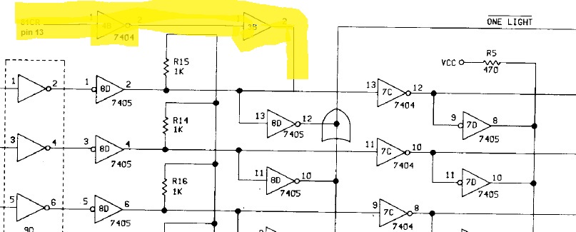
I found an interesting open source project on GitHub that will drive an old Teletype, e.g. model 15 or model 19 that Marc is restoring. It is called TTYLoopDriver if anyone is interested.

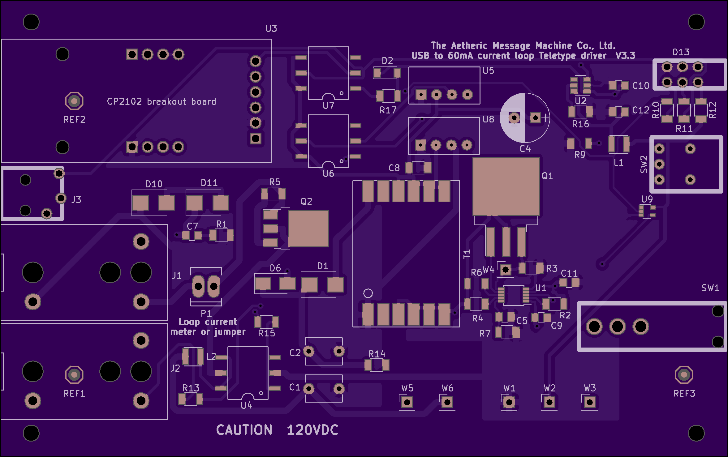
The board design from the GitHub project
It produces the 60ma current using boost converters and a clever idea, that the reason for the 120V DC used with these old machines is to get a quick enough response from the 4 henry solenoid coils. That means that after the coil has ramped up using the high voltage for some milliseconds, it can be held in place by a much smaller voltage such as 5V at the same 60ma current.

I shipped off the design to OSHPARK to fab up three of the PCBs (their minimum order is 3), plus placed orders with Digikey and other vendors for the components and case required to build it. The parts themselves should all be here by the end of the week, however the PCBs will take about a week and a half to arrive. More on the project once the boards are on hand.

COMPUTER HISTORY MUSEUM 1401 RESTORATION MEETING

We continued to troubleshoot the problem on the German 1401 where we receive spurious read checks and validity checks while reading punched cards. Last week we discovered that something was stopping the CPU clock periodically. If a card row was ready for processing while the clock was stopped, the row and its processing was skipped entirely. The card is moving physically and can't stop and wait for the clock to restart.

Today we traced the cause of the clock stopping to some logic involved in processing the data from a row. Handling input-output operations makes use of the overlap registers in this machine, because it was configured with the overlap feature.

That produced some signals which are used in certain cases, such as when doing read-punch joint operations or some mag tape operations. These are blocked by an AND gate which should only let them through to stop the clock in the special case conditions.

This logic is in the Tape Adapter Unit (TAU) which is a part of a 704 computer that was grafted, Dr. Frankenstein style, onto the 1401 to support tape drives. The TAU uses a completely different set of voltage levels and SMS card types. Y logic is true at ground level and false at -6V, using drift transistor circuits called SDTDL which is saturated drift transistor diode logic.

We verified that the special case signals were off, but the overlap pulses were still passing through the AND gate, causing our problem. We swapped the card for the AND gate and the problem went away. Before we definitively declare victory, we would want to reinstall the bad card and see the problem recur.

Unfortunately, someone switched on the airconditioners in the room. This problem is only seen as the processor gets warmer and the AC will make it go away. We were too close to the time for the scheduled public demonstration in the room, so we will have to wait until next week to check for the problem and test out the suspected bad card.

Bottom line, we MAY have gotten to the root of the problem and repaired it. 

Monday, May 28, 2018

Snail like progress finishing up the Documation card reader USB interface conversion

DOCUMATION 1000 CPM CONVERSION TO USB INTERFACE

My right angle cables arrived tonight and I carefully installed one to test out the board fully installed in the card reader. The right angle cord is just perfect, leaving plenty of room for the main connector to the card reader.

Right angle cable provides the clearance I needed
Still, with this board in which I had twisted the socket to restore USB connectivity, I had erratic connections. The reader did pick and read two cards, but kept dropping the PC connection. I have to wait for my new FTDI USB daughterboard and install it before I can be sure that I have any problems other than the flaky board connectors.

Meanwhile, I found a new mini-USB socket in my parts bins, spurring me to solder it onto the second interface card with the previously dead FTDI USB daughterboard to permit me to use this with the other (600 cpm) reader I own.

My solder paste is all stale and dried out, otherwise that would have been the ideal mounting approach. Put paste on the five leads and four grounding pads, then gently heat with the hot air gun until the connector snaps into place on the molten solder. Surface tension is a wonderful thing.

Instead, I had to hand solder this into place. It was very hard because the five leads from the socket do not extend out past the overhang of the connector body, making them very hard to see and reach with a fine soldering gun tip.

I was able to get the connector aligned properly and the ground pads soldered, to hold the connector to the board (as well as these ever hold, which is . . . not very). The challenge then was to get the four active leads of the five soldered to the board traces. The leads are +5, D+, D- and ground, plus a n/c trace.

Unfortunately, one of my four required traces lifted - the D- signal - requiring me to try to do an emergency fix. If I can locate the D- signal elsewhere on the board, I can do a very fine jumper wire from pin 4 of the socket and restore operation. Otherwise, this is truly dead.

Fortunately, I found a 270 ohm resistor that sits between the D- pin of the socket and the D- pin on the FTDI 245BL chip. It is close to the connector, which gave me the chance to tack on a very fine jumper wire and repair the board.

Upper right oval is missing trace, lower left is resistor pad for D- signal
In the picture above, you can just barely see the pin of the connector peeking out, at the very top of the red oval. I had to tack a wire to that pin, then tack the other end to the circled resistor end. If I could achieve the connection to the socket pin, the rest would be easy. 

A blob of solder formed underneath, spanning three of the socket pins. I had great difficulty trying to extract it and wasted 45 minutes fooling with it. I finally decided that the time involved was excessive, given that I had replacement daughter cards on the way which would give me a more solid and reliable board than likely with this fix. 

Sunday, May 27, 2018

Debugged and did more installation of the USB interface board into the Documation card reader.

DOCUMATION 1000 CPM CARD READER USB INTERFACE CONVERSION

A reader pointed me at right angle USB adapters, which have a good chance of allowing me to make use of my interface PCBs as constructed, allowing the cable to exit sideways and not interfere with the connector to the Documation electronics.

 Neither of my interface boards were communicating over USB after I had force fitted the USB cable to the mini (B) connector. I suspected that this was a result of damage to the fragile mini USB connector itself. I verified that by bending the inside of the connector, carefully, and restoring communication on one of the boards. The other was too damaged to resurrect.

I hope the right angle adapters will be safe enough to use with my boards, without stressing the mini USB connectors. When they arrive I will make a determination. The first set I ordered turned out to be regular USB A right angle adapters. The next set I ordered was a regular USB A to regular B right angle adapter. Only now have I gotten (I hope) the correct USB mini right angle to USB A cable.

An alternative would be to remove the connectors and somehow install bare wire from a cable to the board. Since the connector is surface mounted to the board, I would need a method of mechanically securing the cable end, thus some thought is still required for this possible approach.

I did some experimenting with the damaged board and found that it was infeasible to connect the wires directly to the surface mount pads on the board. It would take very fine wire to solder onto the five thin surface pads, then those need to be soldered to the normal stranded wires in a cable, all without a good way to provide strain relief.

My LED holders are here and I proceeded to drill and install the holder into the Documation 1000. The card cage cover can then be installed, leaving the rear cover off so that I can install the board and right angle cable when it arrives.

The rewired LED lights and toggles with the pushbutton, exactly as it should. The board communicates nicely with my PC, although I can't plug the connector with the card reader signals onto the board since my current cable protrudes over the connector space. Right angle connector will (should) be the solution.

EOF state toggled on
EOF state off
TELETYPE MODEL 19 (MILITARY) RENOVATION

We located all the schematics and wiring diagrams for the unit we are restoring - the desk with its confusing myriad of sockets and wires, the transmitter unit and the printer/keyboard unit. We already had the wiring diagram for the REC 30 rectifier that converts the line power to 120V DC to power the current loops used by teletypes.

Teletypes encode text into 5 bit Baudot code, which can be shifted to Letters or Figures since 5 bits isn't enough to encode 26 letters, 10 digits and some other characters like period. One of the 32 codes is assigned to Letters, for example, to shift the machine to one state much as the Shift key on a typewriter shifts between lower case and upper case encodings of each key.

The 5 bit character is sent serially over the line, beginning with a start bit, the five data bits and a stop bit that is slightly longer than the others. Bits are sent by either the flow of a 60ma current (Mark) or no current (Space). The idle state of the line is Mark, so a steady current flows until a start character is transmitted by sending Space for the appropriate time.

The machines are set up to operate at a target bit rate - this machine has the most popular rate of 45.45 Baud (bits of a Baudot transmission) which is 22ms per bit time. Each character has 5 data bits, 1 start bit and 1.42 stop bit times, thus it takes just over 163 ms to send it. That is a sustained rate of a bit over 6 characters per second. Commonly, this is referred to as 60 word per minute speed, with an assumed average character length per word to make the math come out right.

Paper tape is used to store and send messages, in addition to the keyboard of a teletype machine. The paper tape has five holes, to represent the Baudot (actually ITA2) encoding as described above. Since each character on tape comes in with all five bits, but the data is transmitted serially over the line and serially to the printer itself, some form of parallel to serial conversion is needed.

The transmitter unit provides this function. It reads the paper tape and for each five bit character read, it spins a rotary encoding wheel on turn to send the start bit (always Space), the five data bits (Mark or Space depending on the associated hole in the tape), and the 1.42 bit long (31+ ms) Mark that is the stop bit. Thus, it is a parallel in, serial out shift register but done electromechanically.

Transmitter unit of the teletype (paper tape parallel to line serial converter)

Friday, May 25, 2018

Found minor problems with Documation interface; started restoration of Teletype 19

DEBUGGING AND FINISHING DOCUMATION 1000 USB INTERFACE CONVERSION

One of the problems I need to correct is the mechanical interference between the header connector with the card reader signal wires and the mini USB cable. I didn't allow for enough room, thus the cable from the USB connector wants to run right through the side of the header connector.

USB cable interferes with header for card reader connections
My plan to correct this is to desolder the back row of the header that connects my USB board to the interface PCB, then tilt the board upward by pushing down the newly loosened header row and soldering. If it tilts enough, the USB cable can clear the top of my signal connector.

A minor flaw I discovered is in the wiring of the LED that indicates the End of File (EOF) circuit. I wired it between the output of my board and ground, but in fact it should be reversed polarity and wired between the output and +5V. That one was easily corrected.

I know my board is mainly working because when I power it up outside of the card reader, I can talk to it with the PC software over USB and see the EOF status changing as I toggle the pushbutton. It doesn't respond when installed, but I believe that may be because of the USB cable interference issue I covered up above. When the cable clearance is solved I will try again.

RESTORATION OF MILITARY VERSION OF TYPE 19 TELETYPE

Today we helped Marc strip down his military version of the model 19 teletype in order to have all the painted surfaces sand blasted and powder coated to look like new. Much of it could be removed by unscrewing or unbolting, but there were more challenging areas. Some parts were riveted in place or have welded hinges.

The transmitter unit required quite a bit of unsoldering to remove all the parts before the baseplate and covers are repainted. We carefully marked all the wires before desoldering, in conjunction with pictures of the original connections.

The teletype came with a huge power supply (REC 30) which generates the power for the teletype signal line which is a 60ma current loop. The supply has enormous transformers and fuses appropriate for a supply of several hundred watts, yet a teletype current loop should need less than 10W. Later we realized that one supply would be used to power a room full of teletypes, such as in a newsroom.

The desk which is a base for the teletype as a very complex wiring on the back, with 13 power outlets of almost as many types of receptacles connected by a sea of wires. The teletype itself has two power plugs attached, the REC 30 power supply has input, output and motor power plugs, then there are a few switches under the tabletop.

Some of the power outlets and fuses on the back of the teletype desk

It will take us our next session to trace out and understand all the wiring to these outlets, since we need to remove all outlets and wires in order to send the desk out with the other external parts for repainting. I did find a wiring diagram on the web which appears to match the desk. 

Thursday, May 24, 2018

Nearly finished with conversion of Documation 1000 card reader, now debugging

DOCUMATION 1000 CPM REPAIR AND INTERFACE INSTALLATION

A sharp eyed reader spotted an error in one diagram of my last post, which used colored green lines to show the wiring of the modification. I mixed up the two chips, 7404 and 7417, thus the wires ran the wrong way. I updated the diagram, quickly and a bit messily; the correct one has two green and one yellow line representing the wires.

My replacement power receptacle arrived and is installed into the reader. I am still rewiring the machine to connect to my interface board, but could turn on power anyway. Everything worked fine this time, with the machine reading the cards I supplied. I wasn't able to see if it properly read the data but the logic was happy, not detecting any checks during the operation.

I cut up a breadboard PCB and installed a dual row female header, to serve as a good soldering anchor for the 17 signal wires and ground that come from the Documation reader. This will plug into the 2x10 header on my interface board. The next morning, I soldered in the wires to the PCB and work on the rest of the installation.

After all wiring was attached, I checked the connectivity to the proper sockets that originated the signal, to be sure I wired the proper signals to each pin of my connector for the interface board. That took a bit of time to work through but everything was correctly routed.

The interface logic will also need connections to +5V, a SPST pushbutton, and an LED. The button and LED are used to indicate end of file when reading in card decks. I drilled and mounted the pushbutton on the front panel of the Documation, with a plan to drill and install an LED holder above it once my holder hardware arrives.

The wiring was installed from power, ground, the pushbutton and placed near where the LED will go in a few days. Those wires are screwed into the interface board on a terminal strip. The last step in the installation is to arrange a secure mounting for the interface board, above the control PCB inside the card cage.

I chose to use some cardboard spaces above and below my board, thus insulating the two adjacent PCBs from my wires or circuit board. The board is held nicely in place between the cardboard spacers above and below.

Board installed in card cage

The code needed to be loaded into the SX28AC controller chip, using my programmer device. I downloaded the Parallax SK-Key editor and tool, which let me assemble the code from Brian Knittel and then load it into the chip on my interface board. I completed both boards, which are now ready to install and use.

I bought a short adapter cord that will hook to the mini-USB on my interface board and presents a full size USB socket for the connection to an external PC. This completes the conversion of the Documation reader. It connects via USB to the CardRead program on a PC, which will control the reader and capture card images onto PC files. The EOF pushbutton and confirmation LED allow the operator of the card reader to confirm the state of the interface.

EOF button mounted, LED awaiting lamp holder assembly
With everything installed, other than the LED holder, it was time to fire up the reader and test out the functionality. The Surface Pro does see the USB board and assigns it a COM port. Unfortunately, the software on the PC complains that it can't communicate with my interface board, so something is wrong. Further, the EOF button doesn't toggle the LED on and off. I will debug it with the second board, outside of a reader. 

Tuesday, May 22, 2018

Working on Documation readers and interface installation

DOCUMATION 1000 CPM DESIGN IMPROVEMENT AND DEBUGGING

I scoured the board where I was going to add the daughter card and modification, hoping to find a spare gate I could use on an existing chip. I realized I didn't need a NOR gate, just an inverter, because the two inverters I am modifying are open collector. Therefore, if I pull the link between them down to ground, it will block recognition of holes in row 12.

Taking the signal Col81 which goes high when we are at the time just past the last column of data, putting it through an inverter and wiring that to pin 13 would give me the same effect as my prior modification. There are hex inverter chips with unused inverters, but all of them are ordinary, not open collector. The open collector 7405 chips are fully used.

I widened my search to look for any other open collector chips on the board which have unused gates, as I might be able to make that function as an inverter. Aha! There is a open collector buffer chip at 3B, a 7417, which has unused gates. If I route Col81 through an unused ordinary 7404 inverter on 4B and then through the driver at 3B, I will have an open collector signal to tie to pin 13 of chip 8D which already has a pullup resistor.

My modification highlighted by yellow above
This will require a wire from Col81 to pin 1 of 4B, a wire from pin 2 of 4B to pin 1 of 3B and a wire from pin 2 of 3B to pin 2 or 13 of 8D. A clean rework without the need for a daughtercard. I can pick off Col81 (actual signal name 81CR) from the backplane pin 13, since the signal normally is not used on this Control card.
Wiring of the modification to allow right hand notched cards


The tripping breaker may be a leaky starter capacitor for one of the two motors, probably the vacuum/blower one since it only trips when that starts up. Hard to get to it but I will remove it and do some testing. Shouldn't be hard to find a replacement if that is the problem.

DOCUMATION 600 CPM INTERFACE INSTALLATION

I want to mount my new board inside the card cage atop the Documation reader, since that shields the other logic from power supply and motor noise There is plenty of room to place it and easy access to the signals that currently run to the connector on the rear of the machine. I can add a USB connector on the backplate easily.

Cardcage - bottom slot for modified control board - space under 3 for my interface board
Backplate to be modified to put USB connector left of remote switch
The signals that run down to the connector on the back of the machine emanate from the control card in the bottom slot and the clock card in the top slot, wired to the sockets at the rear of the card cage on the left as looking in from the front.
connector on control card (right) has data and pick signals
Status signals on Clock card connector on right 
While the signals above are show with two wires (e.g. Mock and Mock RTN) they are not differential signals, simply twisted wires with one signal and a ground wound around it. All the grounds are tied together to DC RTN, thus I can ignore the RTN lines where they hook to my board as long as I have one ground connection.

I am starting with the 1000 CPM machine first, to figure this out before I put the working 600CPM machine out of service.  I have begun to remove the wires from the connector on the back panel and pull them up into the card cage area. It was a slower process as I had to cut away and remove the outer plastic sheath binding together the various data wires.

Once through I can trim them and solder them onto a connector to push onto my interface board. I will start on this Thursday, as daylight is fading, I am working outside and I will be at CHM tomorrow working on the 1401 systems.


Monday, May 21, 2018

Beginning to install USB interface into Documation card readers

DOCUMATION 1000CPM READER ISSUES

Having built both boards, it was time to install them into the two card readers I own and test them out. The faster of the two reads at 1000 cards per minute, although I have not yet used it. I decided to work on this one first.

First step was to hook up power and verify basic functionality - at least the ability to develop vacuum, blower pressure and to recognize the proper states of the machine. That was the plan, but the power cord was incompatible in an odd way.

The other Documation has a NEMA ML-2R receptacle - this has two curved blades and a hollow center tube for ground. The plug ML-2P is the female side for the hot and neutral blades plus a male center ground pin. That is the standard configuration of the NEMA ML-2 connectors.

The 1000 CPM machine has a receptacle with male blades AND a male ground pin, which won't mate with the standard plug. I have ordered a standard ML-2R receptacle and will install it when it arrives.

In the meantime, I wired up the plug directly to the machine and turned on the power. The power light lit up, in stop mode, with no vacuum or blower. This is the normal condition it should be in. Once cards were placed in the hopper, I hit the Reset button which should spin up the vacuum and air blower in preparation of Pick commands from the interface.

The vacuum, blower and card movement mechanisms spun up, although I could hear some rubbing or grinding which suggests either lack of lubrication or bearing issues. This was mostly good news, although the circuit breaker tripped after about 30 seconds. I tried it a few times, always with the same result.

Time to pull it all apart and begin checking out the power supplies, filter capacitors and motors to determine what is causing the overcurrent. I am hoping it is bad filter capacitors, but we shall see.

As built, the Documation card readers have a design flaw that will suffer false read check errors if the punched cards being read have a diagonal notch on the right side of the card. While most cards have a left side notch, there is no reason that a right side one can't be used. Unfortunately, the notch allows enough light to leak through that the logic believes the card has cleared the photocells too early.

The checking logic of the Documation tests at certain times to be sure the card is moving through appropriately. When the card edge first reaches the photocells, it blocks one or more row cells and starts the timer for reading columns.

The first check is when we are at column 0, the one before the first real data column. The presence of any light on any row is an error, since the card should not have any holes at this position.

The second check is when the card reaches the column after the end, column 81. Again, there should be no holes punched so the logic tests that against the photocell signals. This is where we have our problem with right notched cards, since the row 12 photocell picks up a little bit of light and triggers the read error.

The final check is at the time of column 84, which should be past the end of the card. Indeed, the test is that all 12 rows should see light, otherwise the card timing is off.

I developed a fix for the readers, implemented in my other reader and in Marc's machine. I block the signal from the row 12 photocell when we are at column 81 time. The only time this fix will miss an error is if the card has only a 12 punch in column 80 and is off by one position. Hopefully, the column 84 check will correct for this, but it is an extremely rare error.

In practice, decks are read twice, verifying that the same data is captured for every card. This would catch a problem if the unlikely situation occurred where my fix blocked a read check that should have occurred, since the slippage won't happen the same way twice.

To make the fix requires me to introduce a NOR gate at one point in the circuit that tests for any lit row. This happens at the open collector inverter chip at 8D, where the output of one inverter (pin 2) is routed to be the input of the next inverter (pin 13). This path is a trace that runs directly underneath the chip, so to cut it I either have to remove the chip temporarily or cut and twist up the leg of the chip.

I pulled the chip and will clean up the board, then wire in a small daughter card with the NOR gate on it. The NOR gate is connected to the Column81 signal as well as the inverter output of 8D pin 2, with the output of the NOR gate connected to 8D pin 13. The card also gets connected to +5V and ground of course.

Chip removed, time to do some cleanup and cut the trace
Looking at the trace, however, shows me that I can't just cut it. The chip, a 7405, is an open collector hex inverter. That means that each of the inverters needs a pull-up resistor to work. I can see that the pull up resistor is connected to pin 13, then through the trace to pin 2. If I cut the trace between 2 and 13, then there is no pullup for the inverter whose output is 2.

I could go to plan B, where I twist pin 13 of the chip up so it doesn't touch the pad. I can then take the signal from the pad over to the NOR and bring that NOR gate output back to the twisted up pin of the chip.

However, there is an easier way, where I do cut the trace. The wire from pin 2 that runs to the daughter card will get its pullup from the small card, and the original pullup on the main board will serve as a pullup for my NOR gate. I chose a 7433 chip, which is an open collector NOR gate, which works perfectly for this purpose. Thus, I only have to run wires from the pin 2 and pin 13 pads over to my daugther card.

The daughter card gets its Column81 signal from the backplane connector, a simple matter of tapping the trace as it comes out of the socket. The +5 and ground rails are easy to access to complete the connection of the new boards.

I have the parts for the daughter card on order, which I will finish up as I install the new interface board. Before that happens, I will switch over and work on the 600 CPM model, which I know works because I recently used it to read 7000 cards. 


Thursday, May 17, 2018

Soldering together my Documation card reader interface, plus diabolical soldering challenge kit

BUILDING MY DOCUMATION CARD READER INTERFACE

My PCBs arrived today from the fab and I soldered on most of the components. I am waiting on a connector to arrive, at which point I will also install the three decoupling capacitors and begin installing this into the Documation 600 cpm reader.

My interface board, providing a USB link for the Documation card readers
My Documation 600cpm card reader
PREPARING TO BUILD THE SOLDERING CHALLENGE KIT I RECEIVED

While I was working on the 1401 systems at CHM this Wednesday, we met some visitors who were here to participate in MakerFaire this weekend. They will be exhibiting their high speed cameras, able to take video at up to 40,000 frames per second. During the conversation, one of them handed me a soldering challenge kit they had.

This kit is the most diabolical one I have ever seen. The components on the board range from the relatively large 0603 size () down to a capacitor at 008004 which is only 10 mils long and 5 mils wide.

Challenge circuit board with my pinky for size comparison

It includes LEDs as small as 0201 size plus two ICs, the smaller of which is a ball grid array (BGA) device a mere .055" x .055" with nine balls of solder underneath that must be melted. I have routinely hand soldered parts down to 0402 and the larger of the two ICs, but will be quite challenged by the 01005 resistors, 0201 LEDs, the 008004 capacitor and the BGA chip.

I was going to bang it out today but my existing tweezers are just too large to effectively grasp the smallest parts. Too, my weller soldering iron tip is just too big to work well with these parts. I have ordered the smallest tip and some new tweezers; when the arrive I will take on the challenge. 

Wednesday, May 16, 2018

Core memory Arduino shield progress; 1401 spurious card reader checks at CHM

CORE MEMORY SHIELD FOR ARDUINO DEBUGGING

My first breakthrough came after I began to doubt the truth of the claim in the documentation that this was adjusted to 'work with every Arduino'. In fact, the more I looked at the design, the more sure I was that it was only for the Arduino Uno and similar models, not the Arduino Mega 2560 that I was using.

Flashing the Uno with the provided program and plugging in the shield, I got much improved behavior right away. The serial port communication was erratic, but when I removed both NL and CR from the monitor session configuration, the results were appropriate. With NL and CR appended to my input lines, I got spurious complaints about D and A commands that I was not typing.

Using the W and R commands to read and write the 32 bit core, I discovered that only some of the memory is responding. With 8 bits, always the same positions or addresses, I can reliably write and read contents. However, figuring out from this how it pertains to the schematic is much much harder due to the Arduino code being used.

Specifically, the Arduino code reports using address 0 to 37 to address the 32 bits of core. My working bits are at address 8, 10, 11, 12, 14, 15, 25 and 29, judging by the binary address bits reported, but these don't correspond the 37 decimal. The code asks for hexadecimal values for block reads and writes, but I finally recognized that the address was octal, not decimal. 37 in octal is 31 decimal.

Until I can trace the addresses back to specific wires or components, I can't perform any corrective action. I tried laying out the cores in sequential order, either advancing horizontally fastest or vertically fastest, but neither offered illumination. In one of the orders, however, it did give a clue, or a suspicion that this has to do with one or more of the drive lines that have to coincide to flip a core.

If I number the cores, advancing vertically fastest, so that the left column is, from top to bottom 0, 1, 2, 3, 4, 5, 6 and 7, the next column begins at the top with 8 and proceeds down to 15, I see that the cores which work in the column 8-15 are the mirror of the cores that work in the column 24-31, while no cores work in the other two columns.

Tomorrow I will go over all the solder joints and continuity, after I dig into the VHDL and schematic to figure out which physical columns are the ones that partially work. I can begin watching signals with my oscilloscope as I read or write to specific locations. This is going to take time unless I spot some obvious construction flaw that can explain it all.

1401 SPURIOUS READ CHECKS

Our German 1401 system has been displaying erratic behavior when reading cards, with a variety of spurious errors being reported, mostly read checks. That error claims that the number of holes read by the Read Check brushes didn't match the number of holes read by the subsequent Read brushes. However, we saw this error even with completely blank cards,.

In some cases we received validity checks, asserting that the blank we just read was not a valid character. In other cases, the execution of the read command terminated with the CPU logic thinking it had not yet seen all 12 rows from the card.

These problems come and go. We can be scoping away trying to track down the fault when the machine decides to perform flawlessly for a while. Since the errors occur in several types, each triggered by different sets of logic, we can be watching gate A for a certain type of false read check when the machine begins throwing only the other types.


Tuesday, May 15, 2018

Built core memory Arduino shield, which isn't working correctly yet

BUILDING CORE MEMORY SHIELD FOR ARDUINO

I bought a fun kit from  which implements 32 bits of core memory on a shield, a board that plugs onto the top of an Arduino. It arrived yesterday and I began assembly today. The totally frustrating part of the kit is wiring up the core array. This took me much of the day to get right.

First problem, but easily managed, is the very tiny core rings. These are hard to see and to pick up and manipulate. Threading 32 gauge magnet wire through these three times, for the X, Y and sense wires, is quite challenging but bright light, tweezers and superhuman eyesight is all it takes.

Core rings next to a standard transistor for size comparison
Second problem and more frustrating, was the instructions telling me that the enamel insulation on the magnet wire would burn right off with heat. 180 seconds of heat applied by a soldering tool did nothing. With the insulation on, the wires barely soldered onto the board and made poor contact.

I wasted an hour attempting the 'burn off' method before I cranked up the soldering temperature from my usual 630F up to 750F at which point it does a better job of burning off the enamel and soldering. Not perfect but better. Will have to drop the temp down when I go back to soldering sensitive components onto the PCB.

Key to a good looking core plane is tension on the wires to create an even grid of X and Y lines at right angles. Eight cores are threaded onto the vertical (X) wires, after one end is soldered to the PCB. Then, each of the horizontal (Y) wires is threaded through a core such that cores alternate vertically either 45 degrees to the left of vertical or 45 degrees to the right. This pattern is essential to make the coincident current method work properly with the sense wire.

Vertical wires installed with 8 cores on each
My four vertical wires were in place with eight cores on each. The next step is to thread the horizontal wires through one core on each vertical, alternating the angle of the cores, and solder down both ends of the horizontal wire. This had to be done eight times, once for each of the horizontal wires. Tedious work, at the limits of eyesight, but eventually all 32 cores were suspended on the grid in their proper orientations.

The second of eight horizontal wires was threaded, but the core ring broke in two while I was manipulating the wire to the solder pad. That forced me to unsolder one of the verticals, add a ring and thread it appropriately. This can get quite tedious if things go wrong in the midst of the wiring.

Broken core ring
By four PM I had half the cores on the XY grid and needed a break to rest my back and eyes.

Half the cores in place - 16 of the 32 bits
After dinner, I completed the entire XY grid through the 32 core rings and began to feed the sense wire through the cores in a single run. The final step in assembling the core plane is to weave the single sense line through all 32 cores. As this is the third wire threaded through each core ring, it is a bit more mechanically complex.

This was quite, quite difficult. I completed the first 9 cores before I had to take a breather to recover eyesight and patience. The wire has to bend and swoop all through the plane with many reversals.. I made use of forceps to hold the end of the wire that I was threading, then to pull it through smoothly from the other side. Much easier said than done. However, eventually I completed it all.

Once the core plane was assembled, I turned to the rest of the shield PCB, installing four rectifiers, sixteen drive transistors, a dual op amp, a CPLD logic device, connectors and the remaining capacitors. After checking for solder bridges and appropriate connections, I prepared the Arduino with the demonstration software and pulled out a power supply to deliver 3.3V at over 1A to power the shield.

The results were poor - the LED on the shield never lit up, the software wasn't getting any data in or out of the core, nor are the other results from the demo software making any sense. Time to debug this more carefully - ensuring that the X and Y drive lines and sense wire have continuity, then checking connections on the board. In particular the four bridge rectifiers are surface mount and may not have good connections which would block any read or write.

MISCELLANEOUS

My PCBs for the Documation card reader interface were shipped today by OSHPARK. Early next week I will solder up one of them and install it into one of my card readers. Assuming all tests out well, the other reader will get a second and Marc will wire up the third board for his reader.

I am cleaning out items I don't need and came across a Tektronix 466 storage oscilloscope. It is going to a restoration team member who doesn't have a scope yet. Always happy to see these go to a good home. 

Tuesday, May 8, 2018

Archived 7000 punched cards of DNA sequencing

ARCHIVING PUNCHED CARD IMAGES

Another university researcher has contacted us to read some boxes of punched card data from old gene sequencing work. In this case, four boxes of 2000 card each have arrived, although the contents of the last box is half data and half spare cards as padding.

I hauled my Documation card reader and interface over to Computer History Museum where I can process these cards in batches, producing digital files we can send back to the researcher. My reader is capable of processing 600 cards per minute although generally there are misfeeds or other errors that occur often enough that the true reading rate is much lower.

If these fed and read flawlessly, it would take about 15 minutes to archive but I expect the project to take a couple of hours. Firstly, we reread the cards and compare to the stored version to detect any errors, which would push the time to 30 minutes in a perfect world.

More importantly, I expected to experience about one stop per 100 cards based on past archiving efforts, which introduces 140 stops of about 2 minutes to the processing, plus time to load and unload hoppers. I thus assumed the total task will take 2-3 hours, divided into batches limited by my patience.

I had fewer stops that I expected, with boxes 2 and 3, a total of 4000 cards, reading almost flawlessly. Even with the verification errors and need to reprocess some batches, plus the stops due to cards in box 4 that were bowed top to bottom, it took just a bit over 2 hours to deal with 7000 cards.

MOVING ALONG ON DOCUMATION INTERFACE PROJECT

Meanwhile, parts have been arriving - everything but the USB module which is due on Thursday. The PCBs themselves are now in the process of fabrication and should be mailed out to me on May 16th. I have yet to work out the exact mounting process of the board on the back or inside the Documation reader.


Thursday, May 3, 2018

Building card reader interfaces for Documation readers

DOCUMATION CARD READER INTERFACE

I took some time to design and send away for a printed circuit board to build the interface that hooks a Documation card reader to a PC through a USB cable, based on the design by Brian Knittel but with a different USB/Parallel port module since the original he specified is unavailable.

This has a SX28AC controller on the board, making use of a 82C55 IO port device and some support components. This will be placed on the rear of the card reader, replacing the bulky and expensive signal connector from Documation.

My board is 4" square and has connectors to plug in the USB module, connect 5V power, connect to an End of File pushbutton and indicator LED, plus a dual header to connect to the 17 signal wires from the Documation.

Simple PCB for card reader interface
I have all the parts as well as the boards on order, with components for two boards and three PCBs (since that was the minimum order) coming. When it is all here, I will put together two boards and wire these into my two Documation readers. 

My original reader runs at 600 cards per minute while the other is faster, at 1000 CPM. These are very handy when someone shows up with several boxes of data or programs on punched cards.


Labeled the 1053 emulator, looking into repair of IBM 2310 compatible disk drive heads

IBM 1053 (1130 CONSOLE PRINTER) LABELING

I dug out my labeling system and produced labels for the console printer emulator box. The process involves printing images on a laser printer, fusing colored mylar film to the toner, bonding clear mylar over the printed image, dissolving away the original paper, then adding adhesive and rubbing the letters onto their final surface. 


Newly labeled emulator box

DISK HEAD REPAIR FOR IBM 1130 SECONDARY DISK DRIVE

My IBM 1130 system had as an accessory a cabinet with a Diablo disk drive installed. This drive was the rare standard density version, so called because the original disk drive that spawned all the single cartridge drives was the IBM 2310 drive that is built into the 1130. The 2310 drive was a 1MB capacity drive using chrome covered recording heads operating at 1100 bit per inch density.

My diablo drive also operates at 1100 bpi for compatibility with the 2310. Both use 203 tracks, heads on both top and bottom surfaces, and sector pulses to divide one rotation of the disk into multiple sections. The 1130 implements four sectors of 321 words (642 bytes) although the actual disk cartridge has 8 sector marks per rotation. The 1130 ignores every other pulse to make use of just four logical sectors.

The companies which had licensed the 2310 disk drive patents began to improve upon the IBM implementation in a number of ways, such as faster seeking and higher capacities. The high density version of the Diablo drive records at 2200 bpi, thus doubling the capacity of a cartridge while using the same 203 tracks and two surfaces. Almost every Diablo drive is a high density version, incompatible with the original IBM 2310 and standard density Diablo drives.

All alignment cartridges produced by Diablo have recorded patterns for both standard and high density drives, thus I can make use of the alignment cartridges we have to adjust my standard density drive, once the heads are repaired. They suffered a bad crash, scratching the surface of the chrome.

Most damaged of the two heads
The high density drives replaced the chrome with ceramic, which does not gouge the same way that the original heads did. We have been able to clean ceramic high density heads and put them back into surface regardless of the nature of the disk crash they suffered. Not so with my chrome heads.

Head with more moderate scratching
I will examine them under the microscopes to evaluate the possibility of rehabilitating them. I have a chrome head from a different disk drive type, relatively unscratched, as a comparison. My hope is that the surface can be repaired and the disk drive put back into service as my number two drive on the IBM 1130. 

Relatively good head for comparison