I scoured the board where I was going to add the daughter card and modification, hoping to find a spare gate I could use on an existing chip. I realized I didn't need a NOR gate, just an inverter, because the two inverters I am modifying are open collector. Therefore, if I pull the link between them down to ground, it will block recognition of holes in row 12.
Taking the signal Col81 which goes high when we are at the time just past the last column of data, putting it through an inverter and wiring that to pin 13 would give me the same effect as my prior modification. There are hex inverter chips with unused inverters, but all of them are ordinary, not open collector. The open collector 7405 chips are fully used.
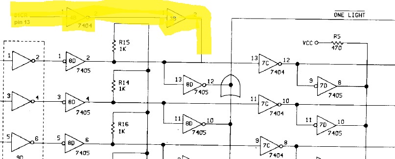
I widened my search to look for any other open collector chips on the board which have unused gates, as I might be able to make that function as an inverter. Aha! There is a open collector buffer chip at 3B, a 7417, which has unused gates. If I route Col81 through an unused ordinary 7404 inverter on 4B and then through the driver at 3B, I will have an open collector signal to tie to pin 13 of chip 8D which already has a pullup resistor.
 |
| My modification highlighted by yellow above |
This will require a wire from Col81 to pin 1 of 4B, a wire from pin 2 of 4B to pin 1 of 3B and a wire from pin 2 of 3B to pin 2 or 13 of 8D. A clean rework without the need for a daughtercard. I can pick off Col81 (actual signal name 81CR) from the backplane pin 13, since the signal normally is not used on this Control card.
 |
| Wiring of the modification to allow right hand notched cards |
The tripping breaker may be a leaky starter capacitor for one of the two motors, probably the vacuum/blower one since it only trips when that starts up. Hard to get to it but I will remove it and do some testing. Shouldn't be hard to find a replacement if that is the problem.
DOCUMATION 600 CPM INTERFACE INSTALLATION
I want to mount my new board inside the card cage atop the Documation reader, since that shields the other logic from power supply and motor noise There is plenty of room to place it and easy access to the signals that currently run to the connector on the rear of the machine. I can add a USB connector on the backplate easily.
 |
| Cardcage - bottom slot for modified control board - space under 3 for my interface board |
 |
| Backplate to be modified to put USB connector left of remote switch |
The signals that run down to the connector on the back of the machine emanate from the control card in the bottom slot and the clock card in the top slot, wired to the sockets at the rear of the card cage on the left as looking in from the front.
 |
| connector on control card (right) has data and pick signals |
 |
| Status signals on Clock card connector on right |
While the signals above are show with two wires (e.g. Mock and Mock RTN) they are not differential signals, simply twisted wires with one signal and a ground wound around it. All the grounds are tied together to DC RTN, thus I can ignore the RTN lines where they hook to my board as long as I have one ground connection.
I am starting with the 1000 CPM machine first, to figure this out before I put the working 600CPM machine out of service. I have begun to remove the wires from the connector on the back panel and pull them up into the card cage area. It was a slower process as I had to cut away and remove the outer plastic sheath binding together the various data wires.
Once through I can trim them and solder them onto a connector to push onto my interface board. I will start on this Thursday, as daylight is fading, I am working outside and I will be at CHM tomorrow working on the 1401 systems.


No comments:
Post a Comment