Wednesday, March 15, 2017

PARC meeting picture, progress and not on the TV 3 tube tester

ALTO DISK TOOL

Here is a picture of the meeting we had at PARC with some of the original researchers who built parts of the Alto.


NAVY TV 3A/U TUBE TESTER RESTORATION

I removed the meter from the tester chassis, opened it up and was delighted to find that the series wirewound resistor was open! As long as the movement itself works, I only have to install a substitute resistor to repair this.

Cover off, next to remove faceplate
Shunt wirewound resistor in series with movement

Resistor is an open circuit!
The meter movement moves fine on its own, restricting the repair to a replacement for this. It was helpfully marked on the face with its precision resistance - 1,640 ohms - which is the value I must shoot for in a substitute.

Anchor electronics parts list
If I combine the 1.6K resistor, accurate to .05% in series with the 40.2 ohm resistor accurate to .1%, the target resistance is 1,640.2 with a max deviation of about 0.84 ohms. The higher value resistor can have a value between 1599.2 and 1600.8 ohms, while the smaller resistor will be somewhere from 40.1598 to 40.2402. I will buy several of each and cherry pick the best combination, both on the low side, to get closest to 1640 exactly.

While I am going there, I cataloged the capacitors that must be changed to finish the restoration. One challenge is that I can't locate one of the capacitors shown in the manual I downloaded. It has clear pictures of where it should be, but the location is somewhat different and there is absolutely no capacitor there.

The manual I found was from 1949, for the TV-3/U while my unit is a TV-3A/U from 1950 or 1951. I bit the bullet and ordered a manual reprint from ebay which should arrive on Saturday. It may be that one of the three capacitors I ordered do not even exist in this unit, but I have visually verified two of them.

Parts in hand, I began soldering the replacement components on the tester. Somehow, while preparing to solder the series precision resistors into the meter, I managed to pop the movement off its bearings. I suspect this is now totally broken, by a stupid mistake, when it was almost salvaged.

The capacitors went on, anyway, so that when I either repair or more likely spend a fortune to replace the meter, the tester will then work. Building the solid state rectifier tube replacement now.

Tuesday, March 14, 2017

TV 3A/U Navy tube tester restoration, still investigating disk tool issuing writing cartridges

ALTO DISK TOOL

Still working through the microcode and hardware to understand each and every cycle I should see on the Alto when it is trying to boot a disk - both successfully with natively written cartridges and failing with the ones written by my tool.

MILITARY TV-3 TUBE TESTER RESTORATION

I stopped by an electronics swap meet this weekend and picked up a US Navy tube tester - the TV 3A/U which was built by Hickok. It measures the gain of the tube, not just the static emission strength like most tube testers, which is important to truly verify that a tube is working properly.

The pilot lamp goes on and one of the two tubes inside has it filaments glowing (the lower voltage 5Y3 rectifier tube) but the other 083 tube did not light at all. I may have a failed tube, but need to check voltages and condition to be sure that something more sinister doesn't exist, either to have caused the failure or perhaps inside the power transformer.

Another flaw is that the meter movement does not budge - it should deflect for the line voltage measurement and also to full scale when the tester is set to the ohmmeter function. The meter has a capacitor across it, which may have failed in a short, or I may have a more pernicious problem given that the line voltage check is a very direct connection.

I checked all the AC voltages coming off the transformer and it is good! Further, there is filament voltage on the 83 rectifier tube but it is stone cold dead. I looked for replacement tubes on ebay, found these ran around $30 each but a kit to create a solid state rectifier that plugs in as a replacement was only $12. It should arrive toward the end of the week.

Next up is diagnosis of the lack of meter movement. Separated meter from circuit - wide open circuit. Something burned out inside. Ouch! These are unobtainium parts. My plan of attack is to first open it up and see if I can find the open circuit somewhere external to the meter winding where it might be fixed. Secondly, I would need to find a close enough alternative and swap the faceplates.

I have removed the meter but have to figure out how to open it nondestructively and then inspect it carefully to find the cause of the open circuit.

Monday, March 13, 2017

Detailed oscilloscope images comparing packs that boot and those that don't

ALTO DISK TOOL

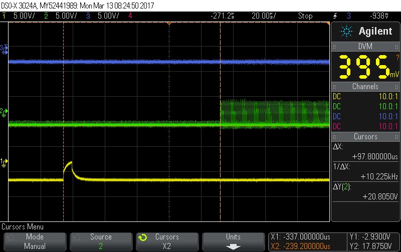
On Saturday we had guests over at the Alto restoration meeting - Bob Sproull who wrote the Alto OS among other things, plus John Shoch again. So many great memories, anecdotes and tips. After they left,we captured traces of the data and clock patterns coming from two cartridges - one that I wrote, which fails to boot, and one with original data patterns which boots fine.

Nothing obvious jumped out of the patterns so far, but I will continue studying them for any significant variance. We began at an overall level without sufficient detail, then zoomed in first to the beginning of the header record preamble, subsequently to the end of the header record with its postamble. 
Alto written cartridge reading multiple sectors successfullly
Cartridge which I wrote, during a failed boot try

One thing that is immediately obvious is some data bits that occur right at the front of the preamble on the Alto written packs. By 'spec' the preamble should be nothing but 34 zero words before the sync word. We zoomed in to examine this in more detail.
Good cartridge, zoom into header record of the sector
Failing cartridge, zoom into header record
The views above show the entirety of the header record, which should proceed as follows:

  • Initial delay before beginning to write (lack of clock pulses)
  • 34 words of all zeroes (16 x 34 clocks with no data pulses)
  • sync word of 0000000000000001 (first 1 bit)
  • two words (32 bits total) of the header record
  • checksum word of the data words XORed together and with see of x0151
  • postamble of zero data until clock pulses end
We zoomed further into the beginning of the preamble to compare the two:
Start of preamble on good cartridge boot
The good cartridges have some random data bits - repeatable exactly on the sector but different patterns on each sector - that start the preamble. Reading a pack involves delaying through 21 words of clocked in data, thus these are not looked at as far as we know. The bad cartridges have no one values at all. 

The cause of this is believed to be residual magnetic flux on the media during the first 25 us of the write operation. On the Diablo heads, the erase head poles trail the read/write head poles by a distance that equates to 25 us at the rotational speed of the disk. When both write and erase gates are turned on simultaneously and zero data words are written, the first 25 us of old information is not erased.

We timed the delay from the sector marker pulse until the first clock pulses is recorded and they are essentially identical. The Alto written packs have some very slight variance between sectors and packs I wrote have sectors that are all exactly the same.

Alto written sector, with delay from SM to first clock pulse
Delay on cartridge written by the disk tool
The tail end of the header record was examined next. This should begin with a single one bit value that represents the end of the sync word, followed by 32 bits of the encoded cylinder/head/sector number, followed by a 16 bit checksum, and some postamble or trailing words of zero.
Good boot of sector zero from sync word to checksum and beyond
Cart that fails to boot, sector zero sync, header, checksum and beyond
The two patterns above are identical except that the postamble clock pulses (those after the last bit of the checksum) are four long on a good booting pack and three long on cartridges that fail to boot. 

First pass through all of this flagged only two difference, neither of which 'should' matter. Residual non-zero stuff at the start of the preamble and the difference of one clock pulse on the postamble. Time to study and count pulses much more closely. 

Thursday, March 9, 2017

Digging into ALTO disk controller interaction with cartridges written by my disk tool

ALTO DISK TOOL

I have a working hypothesis for why cartridges I write cannot boot on the Alto, but can be read back fine by my logic. It centers on a quirk of disk heads that the erase head poles cannot be exactly coincident with the read/write head poles. Typically the erase poles are in back of the read/write gap by a short distance.

The consequence of this spacing is that, when both erase and write head currents are switched on simultaneously. there is a time of about 25 us where any writing flux transitions on the write head would be placed on media that had not had its prior contents erased. The erase poles are lagging.

Requirement to consider the 25 us delay from read/write head position to erase poles

The Diablo drive electronics also requires a minimum delay after WriteGate is turned on, energizing the read/write head, until flux transitions are written, but this is just 2 us. The Alto turns on the heads as soon as it executes a command to write, with no timing circuits to wait 2 us.

Requirement for 2 us minimum delay from WriteGate to first transition

The Diablo manual recommends that a write operation wait 25 us after the sector mark before turning on write and erase heads to write data, and also leaves the write and erase current on for 25 us AFTER the next sector mark arrives. This produces an erased and written swath that fits exactly between the sector marks.

Green circle shows lagging delay of erase head poles behind SM and read/write poles
This is not how the Alto manages the disk, however. On the Alto, every time a sector mark goes active, the disk sector task checks for a match of the cylinder, head and sector specified in an active write command. When there is a match, the disk word task is woken up and the disk sector task goes to sleep, only to awaken at the subsequent sector mark.

The disk word task sets the state for read or write, sets up the count for preamble words, and then goes to sleep. It is awoken when the write shift register has written out sixteen data bits (these are all zero values in the preamble). The preamble on the first record of the sector is 34 words, so the task is woken 34 times before it moves on to write the sync work and the rest of the sector.

Thus, we will have data written essentially immediately after the sector mark occurs, bit cells with one or two pulses depending on whether it encodes a 0 or 1 bit value. This is very different from the recommended method in the Diablo manual.

The way the Alto handles a read operation is the same as write in the disk sector task, where it just matches the address and then fires off the disk work task. The disk word task will be interrupted every time the read shift register has shifted in 16 data bits, a 'word time'.

Reading the first record of a sector involves an initial delay, where the disk word task is woken 21 times as a delay counter, not looking at the data being read, then begins looking waiting for a sync word. That will involve some number of all zero words, which are ignored, until the pattern 0000000000000001 is seen.

Alto format on disk

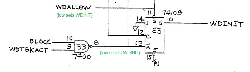
The error I am experiencing occurs quite early in the disk word task execution, when it is looping waiting for the 21 word times to expire. There is a status bit init or wdinit which is on during on of the first invocation of the disk word task, causing an error condition.

That line wdinit is switched on at all times when the command line wdallow is off. Once wdallow is on, the state of wdinit is reset if the word task is going to sleep, i.e. block signal is on during a word task execution.

Init state on for first pass of word disk task, then reset
My error condition is occurring while the wdinit condition is still on, but the microcode task is trying to count down word times from the disk drive. It will shift some value into the read shift register every time the ReadClock signal from the drive pulses, then after sixteen of those clock pulses the register is full raising wddone and forcing a new task execution.

74161 counts up to 16 bitclock pulses then sets WDDONE
The wakeup logic is all reset when the wdallow control signal is low. When the counter of bit clocks gets to 16, it sets wddone which toggles on the left FF. That FF changes asynchronously to the system clock, driven by disk drive ReadClock signals, so the next two FFs serialize this into the Alto clock domain, After two cycles, the wake up signal reaches the top NAND gate and awakens the disk word task.

Wakeup logic above init state FF
 The wdallow signal is set by the hardware when a microcode instruction specifies the ldcom control signal. That is generated by instructions setting a specific value in the microinstruction F bits.

LDCOM sets up WDALLOW signal
F bits select LDCOM signal

Now what I need is a listing of the assembled MU code (MU is the microcode assembler) to let me see how it uses the F bits and bus to set wdallow on and off, in relation to the start of a disk transfer.
The existing listing I have is only of the source code, which is pretty opaque.

Annotated microcode source for start of disk read in disk word task
Until I get get the generated output include microinstruction ROM addresses, to correlate this to the logic analyzer traces of the disk boot failure, it is hard to zero in more on the cause of the problem. 

Saturday, March 4, 2017

Archived a number of Alto cartridges, attended a working session at Xerox PARC, and made good progress on ethernet tool

ALTO DISK TOOL

Good work day today working on the Alto, archiving and verifying each cartridge on hand. The cartridges that I write from my tool are still not booting, however, even though my tool will read back the contents word for word.

Ken Shirriff's ethernet tool is now successfully reading every ethernet packet that the Alto receives, but flaky problems on his BeagleBone board make the transmissions bunch up all the manchester encoded transitions. Code that used to work is now failing the same way. He traced it to a timer which expires instantly rather than waiting for the programmed interval. He plans to get a second board and determine whether he has board problems

We rode over to PARC (the Palo Alto Research Center, a Xerox company) and had a great free form discussion among a number of PARC researchers who were involved in the Alto. On our side we also brought the CHM software curator, who hopes to create a center to study software on these systems.

Finally, we had a visit from John Shoch, a venture capitalist who spent 14 years at PARC, having been recruited by Alan Kay. John is now a trustee of the CHM and was president of a division of PARC before he moved to VC work.

Many great stories and lore, as we discussed ways to demonstrate Xerox Alto and possibly successor machines. Nothing firm but several interesting ideas were floated.

When we returned to Marc's lab, we brought nine more cartridges with us to archive. We had successfully archived the five we had on hand before this, but we have a strong discipline for new cartridges. We open them, clean them scrupulously and carefully examine the surface condition. This takes about half an hour per cartridge, time we didn't have tonight.

The last work we did was to collect some diagnostic information to figure out why the cartridges I write cannot be booted. We quickly found that some condition occurs that the Alto controller card does not expect and the read is aborted. It is while it is reading the preamble, a predetermined count of incoming words that should all be x0000, but the hardware is seeing a non-zero word.

Likely this is a timing issue, where my reading logic ignores the contents of words during the preamble so it happily detects the sync word and rest of the sector. I will be studying my notes and the logic in my disk tool to see if I can figure out what might be happening.

When we meet again, we will record the disk bit stream coming from the drive and compare both successfully booting packs and cartridges that I wrote which all fail to boot. If we can find the variations, I should be able to update the tool and write packs that work. 

Thursday, March 2, 2017

Signal not getting through 3.395 MHz Crystal Filter on HW-100, then it is

Busy as usual, with CHM work yesterday on the 1401 systems, meeting this evening of the microwave experimenters group 50 MHz and UP, Alto restoration tomorrow, lunch panel discussion at Xerox PARC tomorrow, etc. 

HEATHKIT HW-100 SSB TRANSCEIVER RESTORATION AND MODIFICATION

I looked closely at the ALC voltage generating circuit underneath the final amplifier section. The 3.3M resistor is frequently cited as a cause of problems, but it measured fine when taken out of circuit. I then looked at the diodes that are part of the circuit and found the leads were all corroded, looking like they had burned or were badly eaten by something. 

I yanked one out of circuit and it tested okay, but the part is cheap enough that I bought replacements for all of them. Clearly these do not age well. I rewired the entire ALC generating circuit and checked it out, but the results are the same.

Back to tracing the signal through the transmit chain. I see the BFO (carrier oscillator) producing its appropriate frequency in Tune and CW, with that nulled out at the balanced modulator when in USB and LSB. The isolation amplifier V2, which is essentially an impedance matching circuit with no gain, yields about .5V P/P at max gain of the Mic/CW pot which seems reasonable. 

Next up, the signal will pass through a crystal filter to narrow its output to solely the 3395 KHz range with just over 2.1 KHz either side, down 6 db. I watched the signal at the input and output of the filter next. There should be a drop of about .03 V P/P across the filter. 

Ah, very interesting. The input signal is there, but zip on the output. Perhaps the crystal filter is dead. First, I will measure the actual BFO frequency with my frequency counter to be sure that I am seeing 3395 KHz. If it is off by more than 2 KHz, the signal passing through will be so attenuated that it is effectively zero. 
Typical crystal filter design
So, two possible causes of what I see. First, the crystal filter my be defective, perhaps one of the internal crystals is no longer working or has drifted too far off target frequency. Second, the input frequency is too far off the passband and is correctly blocked. If it is a bad filter, I can get a higher quality one for about $40 on eBay, from the SB line of transceivers, which is fully interchangeable. 

I can't get enough gain on the frequency running into or out of the isolation amplifier to lock up my frequency counter, thus I can't measure the frequency. I will revert to my oscilloscope again and look at the signal right off the output of transformer T1 before it goes into tube V2. This was running high enough that it should trigger my frequency counter but it didn't. 

Using the scope, I saw that in Tune mode, the BFO was running at some off frequency, while CW, USB and LSB ran at proper values. I tracked the signal at the output of the crystal filter, which did appear in CW mode. Suddenly, Tune mode was on frequency and passing through the filter!

This is enough to make me question everything I have been seeing and testing. If the BFO is not dependable, the rest of the transceiver is certain to perform improperly. It was almost time for me to head over to the microwave club dinner, a good time to put this aside and look with fresh eyes another day. 


Wednesday, March 1, 2017

Looking for ALC level problems in HW-100

HEATHKIT HW-100 SSB TRANSCEIVER RESTORATION AND MODIFICATION

One issue I have had is lack of any motion on the meter in Relative Power mode, which turns out to be driven by circuitry right next to the components that develop the negative ALC bias voltages that will lower the amplification of the isolation amplifier V2 and the first IF amplifier V3. 

My guess on the relative power meter is that I am not delivering a strong signal to drive the final tubes, thus there actually is virtually zero power. This is suggested by two data points - lack of any heat from the dummy load hooked to the antenna, and lack of change to the plate current.

This developed ALC voltage is used when in LSB or USB mode, but the MIC/CW gain control sets the bias voltage for CW ot Tune modes. I can see the voltage from the control swing from -10 down to 0 as the control is advanced. I must look at the ALC lines and voltages more thoroughly.

To recap, I know that the carrier oscillator is producing its beat frequency oscillator (BFO) output and that this is delivered to the balanced modulator circuit. I know that audio is delivered to unbalanced the modulator and that it is switched to unbalanced mode while in CW or Tune.

The resulting signal is reaching the transformer that delivers this modulated BFO to the isolation amplifier V2. I don't see the signal amplified by V2, which blocks it from reaching the IF amplifier and moving on to the first transmitter mixer where it will be mixed with the tunable VFO that selects specific frequencies for reception or transmission. 

V2 and the first IF amplifier V3 are tied to the ALC voltage, such that the amplification is reduced when high power is detected in the final amplifier tubes V8 and V9. It appears that the circuitry is forcing the tubes to nearly zero gain, incorrectly, since we are not generating any real power to the antenna. 

The gain is forced down by two separate mechanisms - the ALC voltage from the finals when in USB or LSB mode, and the MIC/CW gain control when in CW or Tune. I can't produce any relative power regardless of the mode. 

V2 is a grounded grid amplifier, meaning the grid closest to the plate (suppressor) is at ground, the BFO frequency is injected as AC swings on the cathode, and the screen grid is at 120V while the plate is at 150. Thus, the electron flow from cathode to screen grid is controlled by the bias voltage on the control grid, which ranges between 0V at minimum amplitude to -10V when the gain is cranked up. 

The bias voltage is derived from a junction with two resistors, a 47K and a 1M value. When I measured the voltage across the 47K, it was spot on, but when measuring across the 1M resistor I have a quite low value, nowhere near 1M. If there is a legitimate resistance in parallel with the 1M resistor, it renders it effectively redundant. This leads me to conclude that the resistance should NOT be this low and something downstream from this line is bad.

Resistor junction with one seemingly bad measurement
I can't imagine how a 1M resistor would drift downwards that much in value, thus I have to look at all the connected components to find which part(s) are off value. I looked at the "GRN" line which comes off the bottom of the 1M resistor and traced it back to capacitors that should isolate it entirely at DC.

One section of the GRN line with isolating capacitors or grids
This originates in the final amplifier section, but is DC isolated, so I moved back towards the 1M resistor and found a short segment that does conduct at 10K but only if there is a leaky or shorted capacitor or tube in the above section. Without the leak.short, the 10K resistor cannot affect the value of the measurement across the 1M component.

Coupling but only if the section above has leaks or a short

Going further back, the GRN line does go through some resistors that are eventually headed to ground, but the other side of the 1M resistor would also need to get to ground in order to have a low parallelled resistance. I measure about 58K ohms so the path I am seeking is not going to be much above that since the 1M contributes very little to dropping the composite resistance.


One path for the GRN line is through the mode switch to supply a bias to the Heath built VFO when in LSB mode, to shift the frequency to the other side of the BFO (carrier) frequency. It is disconnected because I replaced the Heath VFO with the direct digital synthesizer.  We can ignore this.
Irrelevant path to VFO bias using wht-gray wire, which is disconnected
The next section of the GRN path is the source of the negative  bias voltage, which comes from the HP-23 external power supply and our value of the voltage on GRN is the divider with BIAS potentiometer. This sets our negative bias somewhere between about -40 and -130V on the GRN line. 

Divider to deliver negative 
For the 1M resistor to be paralleled down to 58K, I would need something, on the path leaving the 47K resistor at the junction with our 1M part, that has a resistive path to the negative bias line with roughly 12K of resistance. That is the only way we can force the 1M value down to what we measure.

The path from the 47K resistor goes to V7 the driver tube, where it should be isolated unless the capacitor or grid is leaky/shorted.
Isolated section from 47K resistor unless leaky/shorted
The line also goes to the grids of the final amplifiers, but in a way that should be isolated at DC unless we have a leaky or shorted capacitor or grid. Nothing in the schematic shows a route that should connect the path from the original 47K resistor with about 12K of added resistance into the GRN path.

Isolation unless caps or tubes are leaky/shorted
I am going to have to interrupt various parts of the circuit and find the low resistance path that must exist, or my 1M resistor itself has plummeted in value. This will require some disconnections and resoldering - going to be a slow process but I need to find and correct this issue in order for the transmitter section and receiver ALC to work properly.

The 1M resistor itself checked out fine, so the reality is what I expected, that paralleled resistance is pulling down the effective resistance. More investigating ahead.