Thursday, November 9, 2017

Built PC side of the HPdrive disk emulator, watched Ken get the ethernet tool working well

HP 1000 SYSTEM RESTORATION

HPdriver disk emulation facility setup

I picked up a Windows 10 based desktop system, this time with room to install my NI HPIB card. I did have to invest several hours activating and processing updates, plus managing a huge list of downloads automatically triggered by Microsoft. 

Once the system was up to date and ready, it was time to authorize use of test drivers, since the custom driver for the HPIB card does not have a Microsoft certificate ($$). I inserted the card and selected the custom driver, then did some testing. 

As far as I can tell without having it cabled up to the 12821A card in my HP 1000 system, it is working properly. It was listening through the PC card for requests from the minicomputer. 

repairing tape drives in 2645A terminal

I received my Plasti-dip shipment and packed it up to take over to Marc's home tomorrow where we can work on our tape drives (and other things). The concept is that I build up layers of this rubbery material on the capstan, then we turn it down to desired size.

KEN'S ETHERNET TOOL FOR ALTO

Ken found a few timing vulnerabilities in his logic, plus a bug in the LCM's IFS software. The IFS software, when it encountered an error in a TCP transmission, waited expecting the Alto to resend the proper packet but it required a kind of ACK to be sent back to cause the Alto to restart. The timing issues he could address by a few changes to his code.

I watched as he tested it for a couple of hours, ensuring that the race conditions did not cause problems - basically the issues arose when Breath of Life packets were being transmitted from tool to Alto very close to when the Alto was sending a TCP packet. It was quite solid and just about ready to share with others who have Alto systems.

The benefit of this tool is that it hooks to an Alto without requiring an external ethernet adapter, any 3Mbit cabling or any other Alto system. It allows network booting for those whose disk drive is not working properly, as well as file sharing and other functions for regular disk-booted operation.

Wednesday, November 8, 2017

Working on HPdrive emulation, 2262 terminal connector, 7906 alignment plan

CHM 1401 RESTORATION TEAM

I repaired the 001 manual keypunch, after a linkage for the space key had fallen off somehow. It was good that we got it back into service as we had a school visit where the fun activity for the kids was punching cards on the 001 and on the 026 powered keypunches.

Iggy worked on one of the tape drives that tended to flutter the tape in a vacuum column up and down near the bottom, also causing the reel servo motor to hunt around trying to follow the tape position. The problem was in the vacuum activated switch, which had an up and a down set of contacts. 

The two sets of contacts were almost overlapping in operation, fighting each other moving the tape up or down. Iggy bent one set to provide a wider zone where neither was active, thus introducing some hysteresis that settled down the drive. Now, the tape jumps up and stops properly, with the reel motor stopped as well. 

HP 1000 SYSTEM RESTORATION

HPdrive disk drive emulation facility

My PC arrived today, that should have allowed me to configure the NI HP-IB card and install the HPDrive software. To make use of it, I still need to:

  1. receive the 12821A card for the HP1000 that acts as a disk controller
  2. hook the cable between the HP1000 system and the PC
  3. test booting with my current bootrom
  4. burn a replacement ROM with a different boot loader if needed

To my surprise, the HP 8000 desktop unit was actually their Ultraslim type, meaning it has zero PCI slots. A waste, although I will put it to use somewhere else. I found a desktop locally that will be delivered tomorrow, one that has 3 PCIE slots. 

7906 disk drive repair

To complete an alignment of the 7906 per the HP service procedures, I need the following:

  • alignment cartridge
  • disk service unit
  • 50 wire ribbon cable
  • alignment printed circuit card
  • 20 wire ribbon cable
  • special preamp printed circuit card
  • head/index transducer alignment tool

I have the first three items. The fourth, the Head Alignment PCA, was quoted at $300 from one person who owns it. The fifth, ribbon cable, is easy to make. However, the sixth, special preamp PCA, is unobtainable as far as I can tell. Without it, the other parts won't work. I am loathe to sink $300 further with no guarantee I will get a full operational tool.

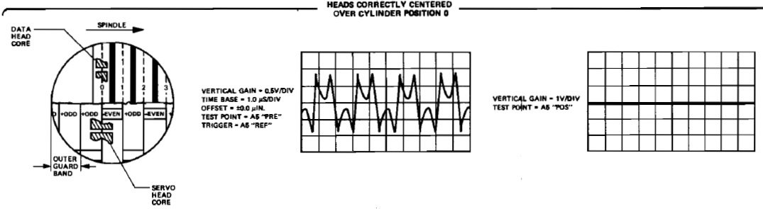
In the service manual, there is a diagram that shows oscilloscope probe points and waveforms for alignment. Unfortunately, these are the servo waveforms that will tell me that the positioning logic believes it is directly over the cylinder on the servo track.

Scope patterns for servo head in alignment, but not the data head above
They do NOT show me the probe points and waveforms that would be seen on the read/write head for the removable cartridge at the same points. I need to see this to tell if my data head on the top of the removable platter is directly over track 245 while the servo is locked on 245 on the lower platter.

For alignment to be possible without the special printed circuit boards, I will need to see a recognizable pattern on the lower data head of the removable platter, assuming that it is properly aligned and the drive is out at cylinder 245. The upper head must be adjusted to recreate that pattern I will see. If it is too ambiguous or I can't make out a pattern to use, then alignment will not be possible.

2262A terminal cable build

The male Centronics 50 connector arrived today, allowing me to complete the conversion of my existing serial card cable to a version that will fit properly on the 2262A terminal. BTW, these terminals are called the ET type because the silhouette looks like the alien from the ET movie.

After soldering the connector onto the cable, I did a test using the tape diagnostic program to write to the terminal in conversational mode. No response, unfortunately. I will need to look at the wiring inside the hood of the connector, as well as the configuration I set up in the terminal. I imagine that something doesn't match. 

Tuesday, November 7, 2017

Various HP 1000 restoration activities

HP 1000 SYSTEM RESTORATION

HPdriver disk emulation facility setup

The post office did find my package this morning, one clean National Instruments PCI based HP-IB board ready to install in the Windows based PC that will arrive tomorrow. The remaining items before I can use this with the HP 1000 are a 12821A HP-IB disk controller card, the cable between that card and my PC card, and possibly a different boot loader ROM.

I am waiting for the seller to ship the disk controller and cable. Since he is in Southern California and I am up in the bay area, it won't be a long transit time.

2645 terminal tape drives

I received my rubber 'tires' to fit over the metal capstans in the DC100 mini tape drives for my terminal. Bought from someone who had plenty of good feedback for using these to repair HP85 tape drives. Those drives use the same DC 100 cartridges for media.

Unfortunately, the assumption that same cartridge would mean same diameter capstan is proven false. These are far to large, swimming over the capstan and therefore unusable for my restoration. Now I have to find a plan B to repair my drives.

The original manufacture of the capstans had them dipped in a 'rubber' compound of some type and then trimmed to diameter by a machine tool. The solid rubber turned to goop over the years. I have to find a suitable means of replacing the missing rubber.

Some have used soft plastic tubing, glued into place, while others have used the soft rubber that is stretched over tool handles. Finally, there is the rubber dip that coats the capstan (Plasti-dip) and can be trimmed to size by spinning the capstan, more like the way they were originally built. Dip is ordered and on the way.

7906 disc drive

I am concerned about how I can accomplish the head alignment for the top head that I removed to clean after the recent crash. I have about half of what is needed according to the HP service manual. Some I suspect I can do without, but there is a big uncertainty at the core.

Aligning the heads on the HP drive is done by attaching the disk service unit (DSU) and adjusting the head position until the value on a meter and digital display on the DSU is at the right point. The DSU indicates distances of 12.5 microinches, either plus or minus from the zero point on the special alignment track on a CE cartridge.

I did buy the cartridge, which has something recorded on cylinder 245 which is read by the DSU to indicate the deviation. In addition to the DSU unit itself, which I have, there are two printed circuit boards that must be installed in the disc drive.

One of them replaces the normal preamp board with a special board that is said to both eliminate the risk of damaging the alignment cartridge and to improve the signal from track 245 to increase accuracy. The first role is apparently by blocking write and erase currents but I don't know what is involved in the second role. Perhaps different bandwidth or response curves?

The other board is added to the card cage in the drive and is named the Head Alignment board. I have no idea at all how this works. It has a 20 signal connector on top onto which a ribbon cable attaches, the other end of that cable hooks to the DSU. 

Besides the 20 signal ribbon cable on the DSU, there is a 50 signal ribbon cable from the DSU to the main interface input of the disc drive. This allows the DSU to command seeks and other operations. 

I don't have either PCB. Without that board feeding the DSU, the meter will have no useful output and I can't tell whether the head is in the right position or not. There is no alternative method mentioned, such as putting an oscilloscope on the read amplifiers and evaluating the resulting pattern. The scope and pattern method is used with most disk drives, such as IBM, DEC and Diablo, but not HP.

Nothing in the manuals or online describes what is written on cylinder 245 of the alignment cartridge. I have no clue whether I could use a scope and determine positioning, since the recorded signal and processing in the Alignment Board is opaque. 

I also lack the tool to move the head forward and back during alignment, but believe I can fudge together something that will be adequate. My DSU can move the heads to cylinder 245, but I don't have a means of evaluating the correctness of the head position. 

Here is what I am thinking as a workaround, unless someone pops up with the two missing boards and can lend them to me. That is an unlikely scenario. Instead I will make the assumption that the second head, which I have not loosened at all, is correctly aligned. 

If I can watch what is read from that head while at cylinder 245, I may be able to discern a pattern that would be useful for setting the top head. If I can't tell from what I see, then I will just set up the head to be as close to the same distance as the second head, visually, and lock it down.

If I can't align and have to accept a rough approximation, it won't affect my operation on my own blank disk cartridges. Whatever I write there I will be able to read perfectly. The issue is that what I write may be off compared to any other 7906 drive, therefore I can't take my cartridge and read it properly on a different system. 

If I even had a theory of operation or description of what the DSU and its two PCBs did, or schematics of the boards, I could probably work out a suitable method of driving the DSU meter myself. There could be ROMs, custom logic chips or other impenetrable components that stop me from reverse engineering the schematics, but if they are all known chip types I have a chance. 

Both the top and bottom heads for the removable cartridge platter are now clean as a whistle. I still haven't satisfied myself with head and platter cleanliness for the lower fixed platter, nor have I finished cleaning those two heads. 

2262A terminal cable assembly

My Centronics 50 male connector is due to arrive tomorrow, after which it take very little time to solder on the six wires from the serial board cable and install the one jumper. The tape diagnostics will tell me if it works properly when I try to use the terminal in conversational mode. 

Monday, November 6, 2017

Working on 7906, disk emulator alternative, and a discussion of my nonstandard board configuration

HP 1000 SYSTEM RESTORATION

7906 disc drive

I did some additional cleaning of the top disk head, using my 99% isopropyl alcohol and Kimwipes, inspecting periodically under the stereo microscope. The hope was that I could get it clean enough without having to wait to use the ultrasonic cleaner at Marc's home. 

The result with an hour of work was an almost flawless head, to the limits of my microscope's resolution. I don't need to wait for the ultrasound bath. I think that one more shorter session just before I reinstall will be adequate.

In addition, I used a bright light to inspect the remaining heads as fully as I could to be sure that once I reinstalled the top head and used an alignment cartridge, everything would work properly. This was quite challenging due to the small clearances but I persisted. 

As far as I can see, the heads are all good, but have a small amount of oxide at the leading edge consistent with normal use. My confidence level is about 80%, but I would really like to get a better view of the heads if I can (and the bottom fixed platter surface). Perhaps a fiber optic camera or similar means of inspection?


Legitimacy of placement of the Firmware Enhancement Board in slot 11 of my system

My system originally came with the Firmware Enhancement Board (FEM) in slot 10, the bottom slot of the IO cage, with a Timebase Generator IO card in slot 11 and other IO cards higher up in the cage. The FEM is not an IO board, however, but a board that holds ROMs that extend the functionality of the system. For example, it provide fast fortran, scientific instruction set and vector instruction set capabilities via ROMs placed on the board.

The way that the HP 1000 works with microcode is to place the address of the next microinstruction on the CRAM bus, which is a set of lines that run to all boards which host ROM. The appropriate board hosting the instruction at that CRAM address will respond by putting the microinstruction on the shared ROM bus, where it is latched in at the start of the next microinstruction cycle. 

Various features, such as the vector instruction set, are placed at a range of the possible CRAM addresses which are reserved for the feature. Other features have different ranges reserved for them, as does the basic microcode implementing the regular instructions, control panel operations etc. 

Boards like the FEM have a number of sockets available to hold ROMs, plus DIP switches to configure the socket to respond to a given range of CRAM addresses. Thus, you can use the FEM to hold different ROMs, or those ROMS could be installed in other ROM board types. The other types are CPU, FAB, WCS or user designed.

The CPU has sockets for the basic functionality of the machine, but adding all the features found on the system requires more sockets than are located on the CPU board. Thus, additional types were created. They are connected by a ribbon cable on their fronts, allowing them to see the CRAM address and containing the ROM bus as a shared tristate bus. 

The first was the Firmware Adapter Board (FAB), which sits just below the CPU board underneath the IO card cage. When the FAB sees a CRAM address it hosts (set up by DIP switches to match particular ROM chips installed in sockets), it drives the output of the ROM onto the tristate bus, otherwise it sits in high impedance (hiZ) mode. 

If the CPU also matches a particular CRAM address it can override the FAB board by asserting a signal BCSEN- that tells the FAB board to stay in hiZ mode even if it matches the CRAM. Then, the CPU would drive the ROM bus. When the CPU has CRAM addresses it does not drive, it stays in hiZ.

The FEM board is a larger board, sitting in a IO cage slot instead of under the CPU where the FAB fit. It can host more ROM chips. When it sees a CRAM address it hosts (based on DIP switches), it drives the output on the ROM bus otherwise it sits in hiZ. 

The ribbon cable that connects to the CPU has a second socket beneath to fit to the FAB, if installed. It also runs up into the IO cage and has three more connectors that would fit ROM cards in slots 10, 11 and 12. 

Writeable Control Store is a ROM board that is actually RAM, so that a user can write or update the contents of the microcode at given addresses. It can be accessed as an IO device for read/write, as well as with the ribbon cable when the system is fetching microcode. Thus this board actually uses the IO cage backplane because it is an IO device as well as a ROM board. 

The priority order for ROM boards is, from highest to lowest, WCS, FEM, CPU and FAB. This is implemented with signals that run on the ribbon cable to all boards. Much like the BCSEN- signal told the FAB board to stay in hiZ even if it matched an address, there are three more signals. 

ECSEN- is driven by FEM boards, to tell the CPU and FAB to stay in hiZ. This is how the FEM has higher priority than the FAB or CPU. If there are more than one FEM boards, the one that hosts the ROM chips for a given CRAM address will drive the ROM bus with the microinstruction and will assert ECSEN- to block CPU and FAB. The other FEM board(s) stay hiZ because they don't match the CRAM address.

WCSEN- is driven by WCS boards, to tell the FEM, CPU and FAB to stay in hiZ. The WCS board asserts that signal only when it will be providing the microinstruction for that CRAM address, otherwise it stays hiZ and leaves the signal off. 

Finally, there is a signal RMX- that is provided for users who design their own custom ROM board - their board can assert RMX- to force WCS, FEM, CPU and FAB to stay hiZ and let the user board provide the microinstruction. 

The FEM board sits in the IO cage but it has almost no connection to the IO backplane. It gets power and ground, bypasses IO priority the same way that a blank jumper card does, but nothing else. The only interaction when fetching microinstructions is over the front ribbon cable that links CPU to FAB, FEM, WCS and/or user boards. 

The front ribbon cable would get in the way of ordinary IO cards, which tend to have cables connecting to the front of them and running off to various peripherals. The ribbon cable would block the connector. Thus, it is reasonable and usual to have the ROM boards installed together at the lower IO card slots - 10 and above - before any IO cards. 

Since the ribbon cable has only three connectors and they are aligned with slots 10, 11 and 12, there is a physical constraint on where the cards should fit. However, there is no reason that particular ROM board types should sit in particular slots. 

The manuals describing how to install the FEM and WCS boards provide ambiguous and sometimes contradictory prescriptions for where to place them. In one place it directs the CE to put the FEM in slot 10 except if there is a WCS and an FEM, the WCS goes in 10 and the FEM goes in 11. 

A different diagram shows slot 10 with "FEM or WCS", slot 11 with "FEM or WCS" and slot 12 with WCS. The operating system needs to know where IO cards are sitting, since it has to address them by their slot number. The WCS is an IO card just like serial ports, so the software must know where it is, but the FEM is invisible to software. 

On a side note, there is an IO priority order analogous to the ROM board priority, but for IO cards it is strictly the slot number, with the lower card having more priority than a card above it. This is implemented by a pair of signals on the IO backplane, PRL and PRH. Any request for interrupts runs down from the card above, on PRL, and is connected through to PRH unless this card wants to assert its priority for an interrupt request. 

Thus, the lower the card, the more it is guaranteed that the processor will act on its interrupt request since it can block or jump ahead of all higher cards. If a slot is left open, no interrupt request from higher card slots can ever make it through to the processor. For this reason, jumper cards are a type of blank IO card that simply jumper PRL and PRH together to keep the interrupt chain unbroken. 

In a machine with an FEM in slot 10 and IO cards above, the highest priority IO card is 11 and each slot above is one step lower in priority. That is how my system came, with FEM in slot 10, and IO cards starting in 11, with some blank jumper cards between various active IO cards. 

I had discovered that the connector on the ROM ribbon cable that sat at slot 10 and hooked to my FEM board was flaky, causing the board to fail to see CRAM requests for microcode it hosted. The next connector up, for slot 11, worked fine, so I simply swapped my FEM for the IO board. Now the first IO card is in slot 10 and my FEM is in slot 11. 

This does not affect the IO interrupt chain because the FEM card (and WCS) also jumper PRL to PRH. The first IO card is a Timebase Generator (TBG), which has no cable connecting to its front. That means the ribbon cable from FEM down to CPU won't interfere with the TBG or vice versa. 

Everything works great, but it doesn't match tradition or the somewhat ambiguous directives in the firmware install manuals, or the experiences of most HP veterans. Therefore I have received warnings that people remember some problem with timing or priority or something with my FEM in slot 11 instead of 10. 

I had to study schematics, ready theory of operations documents and reason through everything before I was comfortable that, while unusual, my configuration is legitimate. I am not sure I have convinced others who remember that somehow this is wrong. 

Of course, if I had a good ribbon cable whose connector at slot 10 wasn't flaky - or if I can acquire a good replacement - I would go back to the traditional placement. There is no reason other than convenience in handling a bad connector for my alternative configuration. 

HPdrive disc emulation capability

I am building up the ability to use a PC as an emulated disc drive, connected to the HP 1000 over an HP-IB bus to a controller card. To do this, I need:
  1. a windows based PC with PCI slots
  2. a National Instruments PCI based HP-IB card
  3. the HPDrive software and HP-IB card driver
  4. a 12821A HP-IB disk controller card for the minicomputer
  5. the cable between the 12821A and the NI board
  6. a suitable ROM boot loader in the minicomputer
I have downloaded the software (item 3) and should have received the NI board (item 2). I expect the PC (item 1) to arrive by Wednesday. While I have ordered items 4 and 5, mailing the payment check, it will take a while before they arrive. I don't yet know if my existing boot ROM loaders will work, but at worst case, Marc can burn a chip with the required loader to swap into my machine. 

Unfortunately, my NI board was shipped by USPS. It had a signature requirement, thus I had a tag on my door on Friday notifying me of the miss-delivery. I used the online system to request pickup on 11/6 at the post office, but they were unable to find it. They thought it might be on the truck for delivery, but of course it was not. Another visit tomorrow and possibly a lost package. I don't look forward to the claim process if that occurred. 

Sunday, November 5, 2017

Work on 7906 disc crashed head, preparing to wire 2262A terminal cable

HP 1000 RESTORATON

7906 disc drive

I removed the top head from the drive, which had suffered the head crash that dug the groove into my disc cartridge. Initially the head looked quite bad, with a sort of metallic smudge and raised area across the head poles. However, I rubbed it a couple of times with kimwipes soaked in isopropyl alcohol (IPA) and it looks quite a bit better already. 

Head with small remaining crash material to clean off

Looking at the head under the stereo microscope, I could see that there is one raised spot right on the read/write pole in the short groove above the main channel in the picture above. There is some dark residue n the short groove on either side of the pole iron. Also, along the bottom edge there are two remaining oxide/aluminum smudges to be removed. 

I will give this a bath in the ultrasonic cleaner at Marc's home, after which I believe it will be clean enough to reinstall in the drive. The cartridge itself is ruined, requiring me to find a new cartridge before I can load heads. 

Alignment is going to be a challenge. The procedure involves a specially written alignment cartridge, much like the ones used with the Alto Diablo drives and others, but one made specifically for the 7906 drive. It also uses a special tool installed on the drive.

I found an HP alignment cartridge on eBay, but can't tell from the listing whether this is for the 7906 drive or the incompatible 7900A that uses thinner platters. Since it was listed for a reasonable amount even if it turns out to be the wrong type, I bought it. Once it arrives I will inspect it to check it for usability with my drive. 

The tool for doing testing and alignments consists of a main panel that hangs on the back of the drive, connected to the main disk interface with a 50 pin ribbon cable. It also provides a special pre-amp board to replace the normal PCB in the drive. That special board is connected to the tool panel with a 20 pin ribbon cable. 
Disk tool on drive, 50 and 20 pin cables hook on top
I have the main tool panel, but do NOT have the special preamp board or the two cables. The cables can be made easily, but the board is pretty hard to find. Since it provides the signals to drive the meter on the main tool panel which is the reference for setting the head alignment properly, I am going to perform some serious improvising. 

2262A terminal restoration

The main task remaining before I can use my 2262 terminal is to make up an adapter for the serial connection. The terminal has a connector block that is quite different from the 30 pin cable that hooks to my 12966A serial board. It is a Centronics 50 female.

Connector on back of terminal
It will require me to first determine what pins are used on the terminal's Centronic connector, then locate the corresponding signals from the regular 30 pin connector. I can see that only a subset of the 50 possible connection points have any metal fingers attached, instead only allowing for 34 signals.

30 pin edge connector on serial cable
Finally I may have to jumper some wires as they enter the 30 pin connector for signals just to set up the board and terminal to communicate. 

Serial cable hood, room inside to jumper connections
After a long time hopping between a number of manuals - for the serial card, 2262A terminal and a general cabling book - I have the desired hookup for the centronics connector. Using the existing cable from the serial card, I can open the hood on the 30 pin connector and get access to the six signal/ground wires I need. 

These six wires will be placed on specific Centronics pins, plus I must jumper pins 36 and 46 to each other but not to any signal wire. The six wires are color coded, making the connections to Centronics easy. 

  • Green wire to pin 48, common signal ground
  • Red wire to pin 42, transmit data
  • Blue wire to pin 50, receive data
  • Brown wire to pin 12, secondary line signal detect
  • Yellow wire to pin 13, ring indicator
  • Orange wire to pin 44, secondary channel data
  • pin 36 provides +5V (logic 1), jumpered to pin 46 for receive line signal detect 
Existing 12966-60008 connector, six wires, to build Centronics 12966-60010 cable

Odd disk drive failure, more debugging of ethernet tool and restoration of 7970B tape drive

ALTO DISK DRIVE RESTORATION

We met today to continue repairing the Diablo disk drives in order to return to archiving PARC cartridges. After cleaning and replacing heads last week, we had spun up one of the CE cartridges loaned by Digibarn to begin the alignment process. As you have read, the drive screeched and wouldn't spin either that cartridge or another known good one.

The edge of the platter was rubbing on the upper edge of a teflon guide bracket when it should have set centered in between the two forks. It appeared the alignment of the mechanical guides or some other part of the head assembly was off.

It took a few hours of analysis, adjustments of everything exactly to the procedures in the maintenance manual and then quite a bit of disassembly before we found the problem. Once we had the receiver mechanism cover removed and had taken a platter from a bad cartridge out of its case, we still were puzzled.

The height of the motor spindle determines the height and plane of the platter. The head assembly is anchored to the same castings as the motor. We couldn't see any way they could have become out of alignment this much so suddenly.

Finally, when we were visually comparing this drive to another Diablo drive, patiently measuring heights, gaps and so forth, we noticed something different about our drive spindle. A part of the CE pack can sheared off due to internal rust on the bolts and was stuck to our spindle!

Disk cartridges have an aluminum hub onto which the disk platter is bolted. Then, a steel ring is bolted to the bottom of the aluminum, to be held by a powerful permanent magnet ring on the top of the spindle.

This ring has held so firmly in place on the spindle that it looked normal, didn't shift at all, and thus we never noticed it. However, it acted as a shim to lift other cartridges up too high. We yanked the heads and indeed there was some oxide abrasion on the upper head from the rubbing when the platters tried to spin. No markings at all on the disk platters, fortunately.

An hour in the ultrasonic bath and some work with isopropyl alcohol soaked wipes gave us back clean heads to reinstall. They were inserted in place but we couldn't use the failed CE cartridge. Fortunately, Digibarn loaned us two of them. A careful cleaning of the platter left us ready to begin spinning it up and aligning the heads.

It was the end of the day already, thus we postponed the remainder of the alignment until the next work session. It will involve moving the disk arm out to track 105, putting the read head signal on the oscilloscope and slowly moving the heads outward until we have a balanced waveform that indicates we are directly over the track.

The head is moved outward by screwing in a setscrew that pushes against a 45 degree slant in the head mount, forcing it to move outward towards the center of the platter. The initial position for heads is about 5 cylinders too far towards the rim of the platter, thus we have to move about 5 mils forward using the setscrew. It sounds easy to do, although next week will tell us whether there are hidden complications.

ETHERNET TOOL DEBUGGING

Ken worked with his ethernet tool, a device which plugs directly into the multipin connector on the back of the Alto that is cabled to the driver card. Normally that multipin connector is cabled to a small box, the Ethernet adapter, which converts the digital signals into the analog modulation on the coaxial ethernet cable.

This tool avoids the need for that, instead avoiding the need for any ethernet cable or adapter boxes. It also converts the signal to use normal 10/100 Mbit ethernet on twisted pair, for routing to other machines or through the internet. The ethernet tool runs a full file server onboard, thus it can be used to network boot, copy files or disk images and use FTP or Telnet from the Alto.

Ken did enough testing to uncover three failure cases that cause the relatively long running diskcopy sessions to hang up. These occur when there is an outbound packet from the Alto to the network tool in close proximity to an inbound packet from the tool, typically a 'breath of life' packet that is broadcast regularly to all connected Altos.

Whether the inbound occurs before, overlapping, or after the outbound packet, the problem occurs if the time separation between them is less than a critical value. Ken is pursuing a new design for the buffer handling in his tool that should be immune to the race hazard failures it is experiencing with the previous code. The tool is quite usable except for these intermittent hangs on diskcopy or other long transfers from Alto to the device.

7970B TAPE DRIVE REPAIR

I gave Marc a 7970B tape drive, previously given to me by Al Kossow. The drive had been working other than failing to detect the reflective marker indicating beginning or end of tape. Suddenly, it stopped loading or responding to the buttons. We knew the lamp needed replacement for the BOT/EOT detection but this was a new symptom.

I found some aerospace stock of the exact lamp to install, but Marc still had to diagnose the failure to load. After checking connectors, power supply levels and all the usual starting points, he moved on to look over the circuitry involved.

He identified a small transistor that drives the Load latch and must switch on to begin the tape movement. While it appeared to work, its turn on characteristics were abnormal compared to a new stock replacement. A semiconductor expert identified this trace as a 'saturated collector' phenomenon, well know as a failure mode caused by a few defects in transistors.
Curve tracer of bad transistor
Good curves of replacement part

With a replacement transistor installed, the drive proceeded to load tape properly and appears ready to use. A simple transistor tester would have missed this defect, reporting the transistor as working properly. However, at low levels of input current to the base it would fail to sink adequate current through the collector, thus never forcing the flipflop to switch on.

Thursday, November 2, 2017

7970 tape drive run through all diagnostics, plus a switch issue fixed

HP 1000 RESTORATION

7970 tape drive diagnostics and repair

I ran the diagnostics for the tape drives and controller, validating timing, movements and correct read/write operation of my 7970E drive. To do this, you have to swap over to a scratch tape at the right time, otherwise you might write over and ruin the diagnostic loader tape.

While everything ran fine during the session, the tests do attempt to address the drives as various unit numbers, from 0 to 3, not just the default I use of 0. Switching the tape drive to respond as the other unit numbers highlighted a defect in my drive. When the buttons for 1, 2 or 3 are pressed, they don't latch into place. Only unit button 0 does this.

Unit select pushbuttons that were failing to latch (1, 2 or 3)
I suspect a mechanical problem in the unit selection switch assembly. Prior to beginning actual disassembly, I reviewed the diagrams and other documentation to understand how it should work. Those weren't of much assistance for the mechanical aspects of latching one button down.

In fact, these can't be disassembled without desoldering them entirely from the PCB. Further, it doesn't appear even then that they could be opened. However, I did see a rod that seems to be the locking bar, which seemed a bit sticky with accumulated dust/sludge.

A shot of alcohol spray freed it up nicely, and it began working properly immediately. I reassembled everything into the drive - the PCB holding the buttons and lamps, a larger PCB that attaches at right angles, three molex power type connectors, plus two ribbon connectors to the control board inside the drive enclosure.