Saturday, January 13, 2024

Adjusting the rotate character selection on the 1053 - part 4

 PRELIMINARY HOMING

The screwdriver set with Bristol heads arrived yesterday and I eagerly set out for the shop to adjust the preliminary homing position. It was much easier with the proper tool - loosened and rotated to the correct position. 


BALANCE LEVER

The balance arm is what balances the negative and positive rotation amounts. To adjust it, one has to set the machine to two different versions of the same unrotated (home) column - 'latched home' and 'I/O home' - so that these produce exactly the same position of the ball. 

Latched home is when the three selector latches R1, R2A and R2 are all activated, thus they are not pulled down by the bail. The R5, not being activated, blocks the balance arm from moving up. These conditions do not impart any movement to the pivot arm and it stays at its neutral position.

I/O home is when the R5 is activated but the R1, R2A and R2 magnets are not. Thus the three positive levers are pulled down, generating at +5 rotation amount, but the cam moves the lever up for the -5 which should deliver exactly the same amount of rotation in the -5 direction. The sum should be zero movement as well. 

This comparison is made with the ball shifted to the 'upper case' side. If the position is different, the balance lever is moved left or right to produce the same position with either version of the home column. 

Adjust by moving left or right

When I checked this setting it was already correct. 

ROTATE ARM MOVEMENT

The leverage of the turnbuckle rod on the rotate pivot arm depends on where it is attached relative to the pivot point of the arm. The rod attachment point is moved up or down until a -5 and a +5 move the ball the same amount from the home position, as judged by where the detent enters the teeth for those two columns. 

Arrow to part that is moved

This one worries me, as I have to set it as high in the slot as possible and I still don't believe I have enough range of swing to fully and reliably accommodate +5 to -5 rotations. 

FINE HOMING ADJUSTMENT

We want the detent tip to touch the sides of the teeth of the ball at a chosen point to maximize the chance that the ball locks to the correct rotate position and no damage occurs to the ball or detent mechanism. The ball is manually rotated clockwise, taking out any slack or slop and acting against the tape tension, and the tip must be to the right of the peak of the tooth by .015" to .025". 

The adjustment is made with the turnbuckle rod that couples the rotation selection mechanism to the bottom of the rotate pivot arm.  This refines the setting that we approximated by making the scribed line parallel to the power frame. 

FINAL PRINT SHAFT TIMING

The timing of the print shaft relative to the print cycle clutch is adjusted by loosening a gear and turning the print shaft manually to check that the detent touches the ball at the best place. A tilt 2, -5 position is hand cycled to the halfway point. 

The print shaft is turned by hand at this point to cause the detent to enter the tooth and then come back out until the detent is 'withdrawn halfway from the slope of the tooth skirt'. No diagram shows this condition so I will have to experiment until I think I have the right point.

Now that the print shaft is at the desired point, we continue hand cycling the print cycle until the ball begins to rotate back to its home column, stopping right when the detent touches the tooth edge. The print shaft gear setscrews are tightened to lock the shaft to this position.


We test that this occurred correctly by hand cycling two different characters with a -5 and a +5 rotate respectively. The detent must just start to rise into the tooth on the left side with a clearance of .001 to .015" from the left edge as it just clears. This must happen for both characters. 

Because of the imprecision of the procedure language above, I chose to hand cycle the -5 and +5 on my own properly adjusted 1053 and observe the detent entering the tooth to understand when and where to measure. 

This is set up now but I remain unsatisfied with the behavior of the rotation mechanism. It seemed to me that if I could increase the range of motion of the whiffle tree mechanism that converts the selection levers to a push or pull of the pivot arm, I might solve the problem. 

One possibility is that I might be able to move the position of the backplate holding the whiffle tree. To look into this, I disassembled the donor typewriter so that I could examine the possibility. It does not appear to be possible to change its position nor would it help. 

During disassembly

The other possibility is to increase the swing of the bail which rides on a pair of cams. In the picture above you can see the rollers on the bail swing arm with the selection latches near the top hanging down to fit under the bottom of the bail. I will look into this more during my next visit to the shop.

GLUING OF THE RIGHT MARGIN LEVER

When I checked my test where I glued the two margin levers of the donor typewriter, the joint was as solid as could be. I then fitted the halves of the right margin lever together, braced them with a small clamp and glued them. 


RIBBON COLOR TAPE I HAVE TO REPLACE


This is the plastic tape that IBM uses to transmit the pull when the ribbon color is shifted from black to red. One of the clips is shown, but the other side tore apart thus even this tape needs a repair. I have no tape at all for the 1053 I am restoring, but so far my tests with various plastic tapes have failed to find a suitable solution. 

Thursday, January 11, 2024

Tweaking the spacing (escapement) for the 1053 and testing solutions to fix other issues

NOTICED ERRATIC SPACING AT TWO ENDS OF THE CARRIER TRAVEL

While I am waiting for the tool to set the initial home position of the golf ball for character selection, I did some testing of the rest of the machine. I noticed that when the carrier is near the left margin, it can fail to space. That means the escapement pawl is not pulled out of the escapement rack by the twist of the escapement torque bar. 

I can see that the torque bar does bend so that it is not at a uniform distance from the carrier. There is no adjustment or way to ensure that the bar is perfectly parallel; the design of the Selectric handles this in a different way. However, there is a center support that seemed to be pushing the bar in a bow so I backed it off a bit.

Escapement torque bar with screw supporting it at center

The issue occurred at the right hand side of the machine as well as near the left margin. The escapement only worked reliably in the center range. This has to be corrected. 

ECCENTRIC STUD FOR ESCAPEMENT PAWL SETS DISTANCE

The design of the rear of the carrier has a bar that rides behind the escapement torque bar and a cam surface that rides in front, to keep the bar confined in a narrow range relative to the escapement pawl and rack. The stud that the escapement pawl pivots on is offset as an eccentric adjustment. One would rotate the stud and lock it into the proper position to achieve a target gap from the escapement bar at the tightest spot. 


Top screw for escapement eccentric stud

Carrier from donor typewriter

x
Underside of donor carrier

I took apart the carrier of the donor Selectric so that I could learn how to adjust the eccentric stud. I discovered that I needed to use a screwdriver on the underside to turn the eccentric; the top merely locks it in place.

View of eccentric stud against torque bar

Screwdriver reaching eccentric stud adjustment

Once that was set properly, the space operation did not work in any location from left to right. Print escapement, the automatic spacing at the end of a print cycle, was working well. What didn't work was the operational clutch driving down a different linkage to twist the escapement torque bar. More exactly, it twisted but not sufficiently to pull the pawl out of the rack so it didn't move.

There is an adjustment to increase the movement of the link to twist the bar, which had a fairly large gap at the rest position which lessens the amount of the operational lever movement that is transferred to the torque bar. I moved the screw down to increase the range of motion, which fixed the issue completely.

Screw to adjust operational space movement

Arm that pulls escapement torque bar

PINSTRIPING AND KAPTON TAPE BOTH STRETCH TOO MUCH

The ribbon color mechanism used a flat plastic tape to pull or release the ribbon lift adjuster, thus moving either the top half or the bottom half of the ribbon in front of the paper. This runs around pulleys in a similar way as the tilt and rotate tapes, but is pulled by solenoids instead of mechanical linkages. 

The tape was missing on the typewriter and I was working on a replacement for it. I bought two kinds of plastic tape to test their suitability for the task - automotive pinstripe tape and Kapton tape. Both were 1/8" wide and also were befouled with adhesive on one side. I thought that I could remove the adhesive if they were going to work out. 

What I discovered is that both of then stretch elastically with just a moderate bit of pull. This would absorb a lot of the movement introduced by the solenoids, all of which is needed to move the lift mechanism inside the carrier. 

TESTED PLASTIC GLUE FOR REPAIR OF RIGHT MARGIN INDICATOR

The right margin indicator was cracked and completely broke as I moved the margins earlier in the restoration. I wanted to test out glues to be certain it will hold the indicator together. First up, I used some plastic glue that I have used in the past when working with plexiglas and polycarbonate. The donor typewriter margin levers were my test bed. They appear to be holding but tomorrow after they have had 24 hours to fully set I will see how firmly they hold. 


If that doesn't work, my 


Wednesday, January 10, 2024

Replacement punch unit for 1442 Card Reader/Punch arrives

CARD READER AND PUNCH FOR IBM 1130

The IBM 1130 system from the mid 1960s was a punched card batch oriented machine as were most of that time. It offered a couple of choices for printers and card readers, with the 2501 and 1442 being the two choices for card handling. 

2501 reader


1442 Reader/Punch

The 2501 solely reads cards, but does so at a high rate (1000 cards per minute) compared to the speed of the 1442 at 300 to 400 cards per minute.  The 1442, however, can also punch cards and thus some installations used it along with a 2501 just for the punching capability.

The 1442 is a good example of IBM leverage of machinery to support multiple computer systems. The basic read/punch mechanism, called SRP or Serial Read Punch, was used with the IBM 1050 communications system and with the IBM 1440 computer system in addition to the IBM 1130. 

The 1050 was remotely connected to a computer and could configure Selectric type printers, typewriters, paper tape readers and punches as well as the SRP. The paper tape punch from the 1050 system was also sold for use with the 1130 as the IBM 1055 and its reader as the IBM 1054 until replaced by a faster IBM 1134 reader - more leverage. 

The 1442 has a hopper where cards are stacked to be processed, a read station, a punch station and stackers to hold cards after they passed through the machine. The machine fed cards and read them at 300 to 400 cpm depending on the model of the 1442, but when punching it was much slower. Blank cards had to be fed past the read station before they reached the punch station. 

When punching, the machine would tightly grip the card using a set of wheels with a ceramic tire that has grit embedded into the surface. For each column the unit would punch while holding the card still, then the wheels would advance the card exactly one column further. 

When the the last column of a card that the program wanted to punch had completed, the machine would feed the completed card at the regular card feed/read speed out to the stacker. The speed of the punching process was measured in card columns per second, available at either 80 or 160 columns/second. Thus punching time was the sum of the time for the grab and punch slow speed movement plus the feed cycle at the high rate. 

For example, if we assume the slower model with 300 cpm read/feed and 80 columns/second for punching and are going to punch 30 columns of a card, the times involved are:

  • 0.375 seconds to punch the first 30 columns of a card
  • 0.200 seconds to feed the completed one out and the new blank one in
  • Total time is thus 0.575 seconds, 1.74 cards per second or 104 cards per minute
A full 80 column card being punched would slow down to 50 cards per minute. If you had purchased the faster model 7 (400 cpm, 160 cols/sec) then the full 80 column card could be punched at the rate of about 92 cards per minute. 

In addition to its relatively slow rate, the 1442 chewed up CPU time as it depended on software to perform functions that were built into the controller logic of the 2501. The 2501 would store all 80 columns of data into core memory without requiring any software intervention. 

The 1442 reader would present an interrupt for each of the 80 card columns being read, then the software had to issue an XIO Read to pick up the data value of that column. An interrupt at the end of the read would present status but that is no different from the 2501. Punching also required interrupts and XIO Write for each column to be punched. 

DAMAGED PUNCH IN MY UNIT

My 1442 reader/punch had suffered damage to one of the two ceramic tire covered wheels that move cards during punching. I tried to fill in the arc that was broken off with UV hardening epoxy with sand embedded, but that was not successful and during all the manipulation to attempt that, the other wheel cracked. These are very brittle and easily damaged. 

SPARE FROM A MUSEUM IS A WONDERFUL SOLUTION

One of the museums that I have been sharing advice during a restoration of their 1130 system had several spare punch units in their collection and kindly offered to ship one to me. It was packed with extraordinary care to avoid any impact on those ceramic tire wheels even with the worst of the abuse that packages receive during shipment. 

The box arrived with almost no signs of trauma, very unusual for such shipments. Even better, the protective packaging worked perfectly and the punch unit was safe and intact inside! Once I have completed the restoration of the current 1130 for the System Source Museum and returned it, I will swap this punch into my 1442 and make sure it is working well. 

UPDATE ON MY PROJECT STATUS POST A BIT EARLIER

Once the current restoration 1130 system is returned to its owner, I will be receiving another IBM 1130 to restore on behalf of the Vintage Computer Federation and its InfoAge museum. My list had only included items currently in my shop that I was or would be working on. I omitted the VCF machine but that caused some confusion from those who knew I was going to work on it. 

While I listed some items that were in my shop that I would NOT be working on and instead dispose of, I did not mention to large and obvious boxes since I am simply holding them for another museum to pick up. I have an IBM Z9 mainframe and an IBM 3490 tape system, plus a few small boxes related to them. 

Finally, I did a bit of work on the pin corrosion issue with the Altaid 8800 kit that I had assembled. By cleaning and repeated insertion/removal into the socket I was able to improve the connectivity enough to get the processor to operation successfully about three quarters of the time I reset it. It was still sensitive to movement. 

I had bought a second 8080 on eBay (from a source that was less likely to be a fake from Taiwan or China) but it looks like I won't need to swap that in. When I had a ten minute break from typewriters later, I managed to get this to become solid and reliable. I hooked up a terminal program and worked with the Altaid monitor and CPM. 

Adjusting the character rotate selection on the 1053 - part 3

PRELIMINARY HOMING

The typeball rotary position is adjusted by loosening a small setscrew underneath the carrier, twisting the ball by hand, assessing where the detent enters the tooth at the home column of the ball, and then tightening up the setscrew to lock in that preliminary home position. 

Red is setscrew, green is wedge on rotate spring end

The diagram above from the parts manual is the only one I found that shows the underside of the carrier where the setscrew should be loosened and the rotate pulley turned. 

The manual warns that one may have to whack on the end of the shaft with a hammer to loosen it up to actually turn with the setscrew loosened. A different manual written by the office products repair group rather than the computer repair group indicates an alternative method where a screwdriver blocks the rotate pulley from turning while the type ball is twisted. It warns that twisting without holding the pulley can snap the metal rotate tape.

I chose to practices this operation on the donor Selectric typewriter that I use for parts and other purposes such as guinea pig. It took a while to find the right place to hold the rotate pulley in position while twisting the type ball, but I did work it out. 

It was obvious that the usual Bristol spline keys (wrenches) I have will not reach the setscrew. There is a major shaft directly under the location of the setscrew and restricted access. I could not see a way to reach from the top around under the carrier and get this done. The setscrew is at an angle which further complicates things. 

Setscrew up in limited access area


direct shot to setscrew is through the middle of the big shaft

Setscrew on the left is at an angle

I had no luck in local hardware stores and had to order a set from Amazon, which means I can't do this adjustment for a few days. In order to determine the correct Bristol wrench size so that when I start the work I will know for certain that the wrench should fit, I disassembled quite a bit of the donor Selectric. I removed the print cycle shaft and clutch, the pushrods that select the rotate and tilt settings and some other things to give me a nice clear opening in which to test with the small wrench I have on hand.

Setscrew to test the fit in the donor Selectric


Opened up cavity to get to donor machine setscrew

I did measure the home position of the ball and found that it was incorrect, off from the home position by one column. This definitely needs adjusting and all the subsequent adjustments rely upon the results of this one. The measurement is take by half-cycling an upper case tilt 2 rotate 0 character; I used the Hooverometer to stop the cycle clutch at the half point. 

Stopping at a half cycle


ball home position offset, needs adjustment

Monday, January 8, 2024

Adjusting the rotate character selection on the 1053 - part 2

 RESTORING ADJUSTMENT OF CYCLE CLUTCH TO SELECT CAM SHAFT

I spent a few hours doing research into the structure and adjustment principles of the cycle clutch to get the select cam shaft in the right orientation to the idle position of the clutch. What I learned, however, was that the clutch and machine were probably already correctly adjusted. Instead, the incorrect selector latch restore adjustment was a measurement error due to an undocumented subtlety when hand-cycling.

The design of the cycle clutch is to have a rubber bumper jam the turning clutch shell which unwinds the spring because its other end is fixed to the always turning operational shaft. The clutch would come to a stop and its momentum would carry it up to and past the idle position slightly, IBM calls this action overthrow. 

The driving force ends at about 170-175 degrees of rotation and momentum takes it to the 180 degree stopping point. When the clutch reaches the idle position on its way to its overthrow point, the check pawl drops into a notch. This will block the clutch from turning backwards as it rebounds off of Overthrow Stop lugs that prevent the momentum from moving the clutch too far forward. 

Check pawl on far left of print cycle shaft, clutch on right

Overthrow stop adjustments

Clutch assembly

What this means for me is that when you hand cycle the machine the momentum does not exist. The clutch does not continue to the full rest position and the check pawl does not yet drop into its notch. Therefore the cams for the selection bail are not at their final low point.

This is why the selection levers are not restoring under the bottom of the bail. They would if the print cycle took place under motor power, but do not while hand cycling. The adjustment manuals do NOT mention this clearly. 

Therefore I will have to set up the cycle clutch as it was, so that it works properly under power. I can test the selection lever restoration under the bail by tripping the clutch after it stops and moving the shaft forward just until the check pawl drops into place. 

The process is:

  • Move the shaft to get the check pawl in its notch and the clutch at its rest position
  • Mount the degree wheel on the print shaft and set it to 0 degrees.  
  • Select a zero tilt, -5 rotate character as this produces the highest resistance to the clutch. 
  • Continue cranking the clutch until it is just beginning to slip
  • Note the degree marking where this occurred. It should be 170 to 175 degrees.
  • Then I will turn further until the check pawl slips into its notch. 
The adjustment is to loosen the screw locking the collar on the clutch, as well as the two Overthrow Stop screws, then rotate the collar until I achieve the above point of slippage.

Next the Overthrow Stop latches must be set. The process is:
  • Have the cycle clutch in its latched idle position
  • Ensure check pawl is in the notch
  • Turn slightly backwards to hold firmly against check pawl
  • Adjust Overthrow Stop latches to allow only .007" to .015" of overthrow movement
  • Perform a second time to set the other Overthrow Stop latch
I again encountered a phenomenon with IBM documentation that is all too common. The documentation is technically accurate but not helpful. In this case it was the description of where to measure the .007 - 0.015" overthrow. Below is the IBM diagram from the manual.

Color marks are my additions

This diagram shows a space of .007 to .015" but what does it reference? The cutout on the right with the red arrow implies that there is a gap to the upper edge of a cutout. First problem - my clutch does not have any cutouts on the right. It does instead have a gap, show as the green rectangle, on the left but only on one side. It is only exposed on every other print cycle since the clutch rotates 180 degrees per cycle.

I discovered that the correct place to measure that gap is down out of sight, where the blue arrow is pointing. the other end of the plastic Cycle Clutch Collar arc from where the measurement was written is the place where that arc bumps into the ledge of the metal Cycle Clutch Sleeve, see the circled area below.


Once I figured that out, I could get the cycle clutch dialed in so that it stopped properly with the check pawl in its notch, and began to slip at 170 degrees into the cycle when powering a tilt 0 rotate -5 character. These adjustments were completed and the operation of the print cycle clutch was verified. 

GOING BACK TO FIX UP THE PRINT SHAFT ALIGNMENT

I had shifted the select cam shaft relative to the idle position. Since that shaft is what drives the gears to turn the print shaft through the carrier, this adjustment needed to be redone to get the key slot pointing at the small hole again. With that complete, I could move forward on the remaining adjustments for rotate selection. 

 -5 ROTATE SELECTION LATCH ADJUSTMENT

Most of the selection mechanism works by the lever tips fitting under the bail and being pulled down as the cams move the bail downwards. However, the R5 selector magnet operates the -5 Rotate Selection Latch which operates differently. That lever will move upwards riding on a cam if it is activated. 


A Stop Bail blocks that movement if the magnet was not activated so that the lever does not move down the cam surface. When the magnet activates, the Stop Bail pulls out of the way permitting the lever to be pulled upwards and its arm ride down to the low point of the cam 

The adjustment insures that Stop Bail can move over the Stop Screw when unselected and that there is no drag stopping it from pulling off the head of the Stop Screw when activated by the R5 selection magnet. 

Bail Stop red, Stop Screw green, adjustment Blue

ROTATE ARM VERTICAL ADJUSTMENT

This adjustment adjusts the rotate pivot arm so that it is vertical when the selection mechanism wants the ball at its unrotated (home) column. The instructions sound simple. They mention that I could use an IBM tool called the Hooverometer to check that the scribed line is parallel to frame, or of course just use any measuring device to see that the top and bottom of the scribed line is the same distance from the frame. 


scribed line
x
Hooverometer

This sounds simple but on the actual printer, there is no section of the power frame next to the scribed line and other parts block the view. At best you have to mentally project a view of the power frame to figure out where it would be if next to the pivot arm, then assess the distance to the scribed line at two points. 


What I was finally able to do was find an inner surface that was flat and parallel to the side of the power frame, so that I could use the Hooverometer to check the distance from there to the top and bottom of the scribed line. 
Flat surface pointed to by green arrows

I verified that this was set to be parallel to the power frame within the precision of the measurement I took. Since this is an initial setting that will be refined later in the procedure, I marked this as complete.


Sunday, January 7, 2024

Adjusting the rotate character selection on the 1053 - part 1

HEART OF THE TYPEWRITER

Printing characters on paper is truly the core of the machine. A command to print a specific character fires the selector magnets to tilt and rotate the type ball to the proper position, as it is being flung forward to strike the ribbon and imprint through that to the paper behind the ribbon. 

The command starts a print cycle, rotating the print shaft to move the typeball and the detents that lock the ball into its final position accurately. Early on in the print cycle, the two metal tapes are tensioned so that they tug on the pulleys under the type ball establishing an initial tilt and rotate. A bit later in the cycle detents enter the triangular teeth on the bottom of a type ball to fine tune the rotary position. Another detent enters four teeth on the tilt rocker to lock in the exact tilt position.

Cams inside the carrier lift the ribbon to cover the spot where the new character will be printed. The ribbon is initially low allowing the typist to see the prior characters on the page; a fixed ribbon positionwould block the view. 

Other cams pivot and accelerate the typeball forward like a hammer so that it strikes the ribbon near the end of the cycle. The ball falls back into position and the escapement is tripped to move the carrier one column to the right. 

Rotate is a complicated process because the machine must twist the ball left or right, establishing one of five left and five right positions as well as the non-rotation home column. Then, the ball must be able to rotate 180 degrees between the 'upper case' and 'lower case' sides of the ball. 

For the IBM 1130, the type ball has upper case characters on both sides of the ball, unlike a typewriter which would have both lower and upper characters. Thus, the letter A will look the same when selected on either hemisphere and takes up 52 of the 88 positions on the ball. However, the other 36 characters (non alphabetic) are divided across the two hemispheres. For example, all the digits 0 - 9 are on the lower case side of the ball with the same position on the upper case side containing ( + < ¬  ) ; * ' " and |. Another eight positions contain only special characters, different on the UC and LC side. 

There is quite a range of tension of the metal tape involved to reach all 22 positions of the ball, if you consider both hemispheres and the eleven selected rotate spots. If this is not done correctly, when the detent enters the teeth on the ball it can lock it on the wrong column, just as a mispositioning of the tilt can lock the ball on the wrong row. 

As I received the Selectric, it had a broken metal tape but I suspect its adjustments were not correct even had the tape been intact, given how many other adjustments I found to be awry. I went with the sequence of checks and adjustments in the Field Engineering Maintenance Manual to be certain I could get the rotation selection to work reliably. This will be a long long process taking many hours in multiple visits to the shop. 

PRINT SHAFT INITIAL ALIGNMENT

The print clutch on the constantly rotating main shaft, driven by the motor, will couple that motion to the shaft to its left. This is passed through an arrangement of gears to the front shaft that the carrier slides across. The shaft has a keyway down its length that locks the various cams in the carrier to the position of the shaft. 

As the shaft turns, the cams inside determine when the detents enter to lock in the tilt and rotate positions, as well as other cams lifting ribbons and throwing the ball forward. The keyway has to be set correctly relative to the rest position of the print clutch, so that the various detent and other operations occur at the proper point in the rotation of the print shaft, e.g. correct time in the print cycle. 

This position is judged from the side of the carrier where the print shaft enters. There is a small hole above and to the rear of the shaft related to the ribbon lift mechanism. The keyway of the print shaft should point to that. A gear is loosened in order to rotate the print shaft to the desired starting point. This was successfully set. 
 
loosen setscrews to adjust the shaft

keyway aligned to hole

ROTATE SPRING TENSION

The tension on the metal rotate tape is what spins the ball to its twenty-two different positions, eleven per hemisphere. The shift mechanism imparts a large tension increase to swing the ball 180 degrees to the 'upper case' side, added to the initial tension and the changes that are caused by the rotate pivot arm selecting negative or position twists of the ball for particular columns. 

The pivot arm moves inward to relax tension to the negative rotation positions and pulls outward adding tension for the positive rotation positions. It is the tension in a watch style spring in the base of the carrier that pulls against the position of the shift and rotary position arms. It has to be sufficient to twist the ball to the -5 column when the pivot arm relaxes inward all the way, but also able to handle the tension of a +5 rotation with the ball in 'upper case' level.

We test the tension by establishing a -5 column on the 'lower case' side and then using a spring scale to read off the tension necessary to move the shift arm off its stop. The rotary spring can have its tension increased or decreased until we reach the right force for this minimum tension position of LC, -5. 

Using spring scale to test tension

A secondary test is performed by shifting the ball to the 'upper case' side and adding the maximum twist of a +5 rotation. The ball must be able to swing to this position otherwise the rotate spring has bottomed out due to excessive tension. This adjustment is complete.

SELECTION LATCH CLEARING BAIL

At the end of a print cycle, the bail that will pull down on selection levers should be back near its lowest point. The lever tips should be able to slide under the bottom edge of the bail and rest there. If a magnet is activated the lever tip is pulled away from the bail, if not activated then the lever will be pulled down as the bail rotates downward during the print cycle. 

This has a check and adjustment that had me worried because on this machine, the tips do not slip under the bail when the print cycle clutch is at idle. I was mollified by the comparison to my properly working 1053 from my IBM 1130 system, which exhibits the exact same condition. When a print cycle begins, the bail moves further up initially and that does allow all lever tips to pop underneath, but the manual was clear in saying this should happen at the print clutch idle point.

I considered the possibility that the print clutch stopping point is incorrectly set, but there does not appear to be any adjustments to address this on the machinery. The cams and fixed parts of the clutch seem to determine the movement of the bail up and down. There is no setting mentioned for the high and low point of the bail either. 

Upon closer inspection, however, I realize that indeed I could adjust the cycle clutch and fix the problem! The shaft with the cams that drive selection and the bail are adjusted relative to the clutch stop point, as well as to a check pawl that locks the mechanism from bouncing backwards upon the stop. 

Looking at the check pawl, which is at the extreme left of the shaft with the selection driving cams, I noticed that the check pawl was frozen in place by stale lubricants. I moved it out and it stayed where it was in spite of the spring trying to pull it back. 


I had to disassemble it in order to clear out the junk and get it lubricated to move freely. Once it was back in the machine, it was time to work on the relative setting of this shaft and the print cycle clutch. When the cycle clutch hits its stop point, the check pawl should have engaged as well but it did not! 

That confirmed that this is the adjustment problem leading to the issue with the selection levers not restoring under the bail at the idle point. When the shaft was rotated until the check pawl engaged, the bail was enough higher that the selection levers all popped underneath easily. In fact, they had the correct gap of .005". 

I loosened up the lock and stop screws on the clutch and was able to rotate the selection cam shaft compared to the clutch. However, I did not figure out how to make the settings so that we had the ideal conditions - cycle clutch triggered, the selection cam shaft moves the bail downward to pull on any unselected selection latches, the clutch comes to a stop after 180 degrees of rotation and the check pawl falls into its slot. 

Cycle clutch in middle, cam shaft to the left

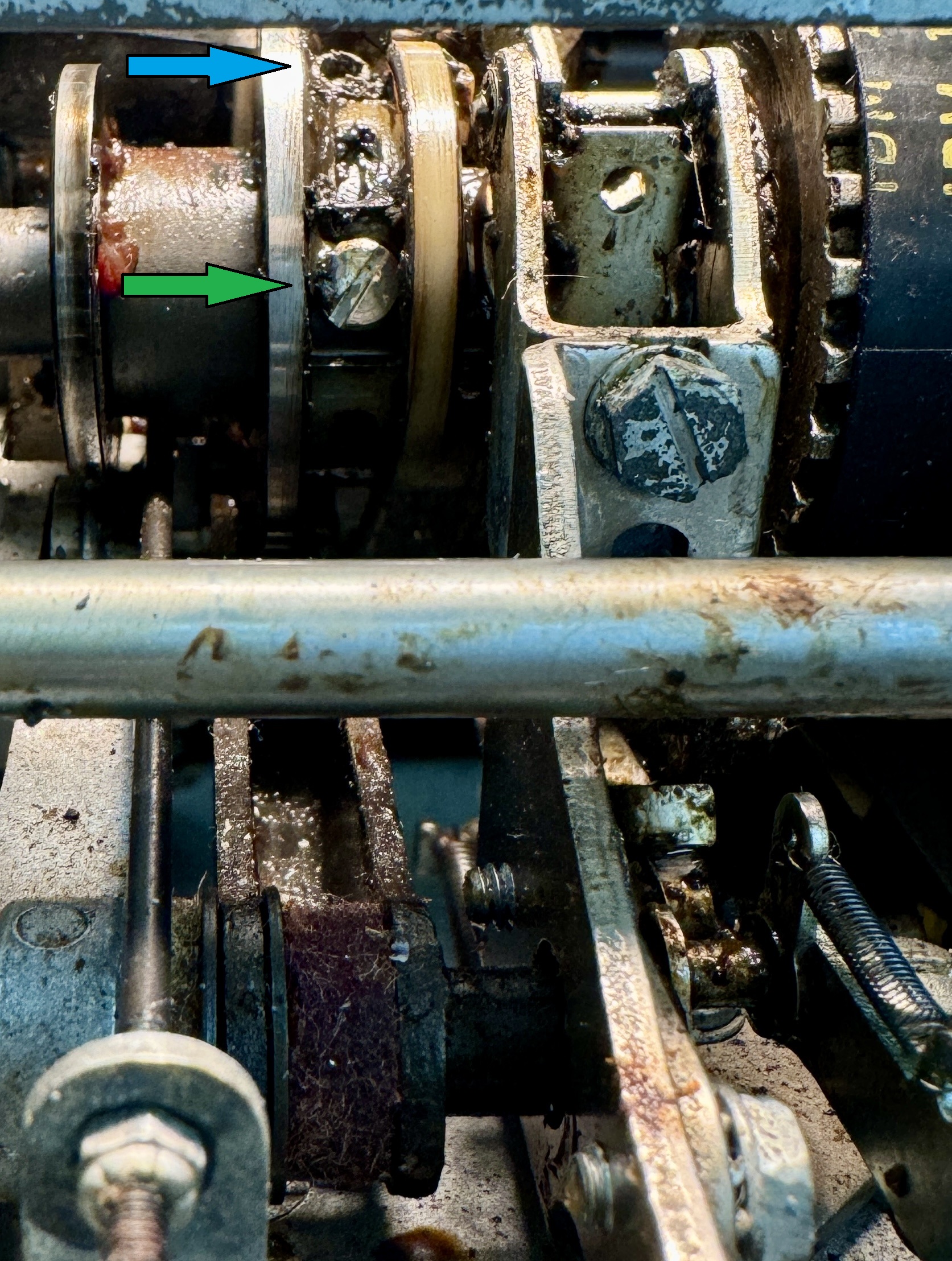
blue is lock screw, green for a stop screw

The manual never mentions the role of the cycle clutch in the bail movement or selection latch restore that is the third item to adjust. Instead it states that I should bend the metal stop tabs down for any selection latch that doesn't restore at the idle point. That would be every selection latch, which didn't seem right to me. I think that would have been a big mistake had I blindly followed the manual.