CARRIER RETURN FAILURE TO LATCH AND CONTINUE MOVING
The carrier return function is a complicated mechanism with a sequence of operations that are necessary for a return to work correctly. It is spread across several areas of the machine as well. The sequence that must occur is:
- Trigger is released for the return operational lever, by solenoid or pushbutton
- The right hand operational clutch takes on 360 degree cycle
- A cam on the operational clutch moves a bail down and up during the cycle
- A lever for carrier return is pushed under the bottom lip of the bail
- The clutch restores the operational lever at the end of the cycle
- The lever pulled down and released by the bail turns an activating linkage
- The early movement of the linkage pulls the rod to arm the margin release bar
- The arming of the bar also latches the activating linkage
- The latched linkage continues to stay down after the operational clutch cycle ends
- The latched linkage holds the escapement and backspace pawls out of their racks
- The latched linkage also forces the nylon shoe onto a spring to power the return
- The powered return winds up escapement cord on the return drum
- The powered return winds the main spring, adding energy for future space and tab
- The winding of the escapement cord pulls the carrier to the left
- When the carrier strikes the left margin lever, it pushes the margin release bar rightward
- The carrier is decelerated by a air cylinder that cushions the carrier to a stop
- The movement of the margin release bar pulls a rod to disconnect the activating latch
- The nylon shoe comes off the spring and the leftward movement stops
- The escapement and backspace pawls re-enter the rack to hold the carrier at this column

 |
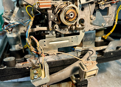
| Green line is Carrier Return Unlatching pushroid |

 |
| Upper pushrod that arms the margin rack |
Early on in this sequence, when the activating linkage starts moving, it should have armed the margin release bar. This did not happen. Without the bar being armed, the latch mechanism is pulled out of the way so that the linkage does not latch. The result is a short movement of the carrier left which ends as soon as the operational clutch cycle completes, not at the left margin.
MOVING PARTS UNTIL THE MARGIN BAR ARMING WORKS RELIABLY
The problem with this mechanism is that the Margin rack Latch Bellcrank can move up and down, shown below with green arrows, which is good when it has to skip over the latch arm to avoid damage, but means that if it pops up where the red arrow is pointing, the Latch Link won't be pulled and the margin rack won't be armed.

This required a bit of experimenting to find the setting that ensured a reliable activation every time that Return was triggered, in spite of its ability to move up and downward in the oval slot on the bellcrank. I did find the best position and this solved the issue.
TESTING UNDER MOTOR POWER CONFIRMS CR WORKS PROPERLY
I used my test rig to fire a Return using the pushbutton and confirm that it zips to the left margin and stops there every time. See the video below.
INTRICATE BALLET OF PARTS INVOLVED IN SHIFT CYCLE AS WELL
The shift cycle is completely implemented in one area of the machine other than a safety linkage that blocks shifts while a print cycle is underway. Still, it is a bit complex and has to be well understood before you can debug problems and correct them.
Like many of the clutches in the Selectric mechanism, a coil spring wrapped around a shaft tightens up and couples rotating motor power to the shift parts, while it is active. When the other end of the spring is blocked, the turning of the motor driven shaft unwinds the spring enough to release its grip and motion stops. Thus, the far end of a spring is blocked to hold every clutch in its inactive state and released to trip the clutch.

The shift mechanism is mounted on a circular cam which drives a pivoting arm to add tension to the rotate tape when the upper case side of the type element is desire or releases the tension to move back to the lower case side. That cam is turned by the clutch we just discussed.

The rotating shift assembly has two stops installed which will hit the loose end of the coil spring and unlatch the clutch, set 180 degrees apart. The outside edge of the round shift assembly has teeth that can be entered by a safety pawl to stop the shift from turning; this pawl is activated while a print cycle is active in order to protect the type element from trying to rotate (in the shift) while pressed against the ribbon, paper and platen.
The outer teeth are extended inward at the point where the clutch should stop for upper case. At the opposite point where lower case should stop there is a inner stop lug fastened. Thus, if the shift release arm is pivoted down towards the inner lug, pulling out of the upper case teeth extension, the shift coil is released and the clutch activates.
 |
| Extension of teeth at top for UC stop |
If the arm is kept down in the path of the inner lug then the coil spring will be grabbed to stop at the lower case position. Correspondingly when the arm moves upwards it first releases the coil spring and then contacts the upper teeth extension when it reaches the upper case position.

Thus control of the shift assembly, both triggering the clutch to rotate and choosing where to stop, is determined by the position of the Shift Clutch Release Arm. That is moved by an arrangement with two solenoids.
 |
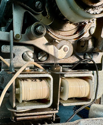
The shift to lower case is activated by energizing the lower case solenoid. The L shaped armature of the upper case solenoid had been held in place because the armature of the lower case solenoid slid over the end of the L and held it down previously.
The spring at the bottom tries to pull the lower case armature over the end of the L and it also tries to swing the upper case L counterclockwise. Thus this spring activates the motion needed to rotate counterclockwise and to slide the lower case armature over the L if it had been rotated clockwise by energization of the upper case solenoid.
The activation of lower case pulls the armature away so that the spring can swing the L armature counterclockwise. This allows the bottom of the Shift Clutch Release Arm to move leftward which swings the part inside the clutch upwards to release the clutch and block the spring at the upper case stop position.


When the upper case solenoid is activated, it pulls the top of the L armature so cause it to rotate clockwise. The upper part of the armature thus forces the bottom leg of the Shift Clutch Release Arm to the right. The Shift Clutch Release Arm upper part inside the shift assembly thus moves down, triggering the clutch and releasing the coil spring when the arm hits the inner stop lug.
TYPICAL ISSUES WITH DOCUMENTATION AND THE NEED FOR MANY HANDS
Adjusting the solenoids and other mechanisms of the shift assembly involves several procedures in the maintenance documentation for the Selectric, but is insufficient to adjust them properly. A common issue with IBM documentation is that you will find it technically accurate in what it says but not helpful in achieving your repair. Instead, you must study the mechanism and figure out the key adjustments on your own.
Each solenoid has two adjustments on its body which determines the armature's closeness to the pole when energized and its rest distance when idle. Also, each of the two solenoids can move and twist on their mounting screws for various left-right spans and rotations. While moving these, the upper case L armature and the lower case armature interfere with each other, latching in various configurations.
I removed the solenoids and made the armature adjustments, which are easy to do by a single person. I then installed them and tried to position them properly. The steps in the manual were all followed by the shift mechanism was not working properly, either not triggering at all or turning 360 degrees back to the same shift position.


ESSENTIAL TO UNDERSTAND EACH SELECTRIC MECHANISM TO ADJUST IT
I then looked and experimented with all the parts of the shift assembly to see and understand how it operated. With that I was aware that the position of the Shift Clutch Release Arm was one of the two critical adjustments and the interaction of the two solenoid armatures was the second one.
The arm upper portion must rotate down to contact the lower case inner stop lug to select lower case and it must rotate upwards the right amount to contact the teeth extension that is the upper case stop lug. The Shift Clutch Release Arm can pivot freely with out the upper case solenoid L armature controlling its motion.
Thus I had to set the upper case solenoid so its L armature put the Shift Clutch Release Arm at the proper UC and LC positions when it was energized and released respectively. Then, the lower case solenoid has to be positioned so that its armature will slip over the edge of the L armature when it rotates clockwise, but when energized will pull free and let the L armature rotate counter clockwise up in the space freed by the LC armature pulling out of the way.
Sounds simple, but there are quite a few positions of the UC solenoid that do not allow the LC solenoid to be oriented successfully, because of the range of motion of its mounting holes. Thus the adjustment involved several trial fits until I got them just right, meanwhile holding the armatures from latching each other into the wrong configuration.
TESTING UNDER MOTOR POWER CONFIRMS SHIFT WORKS PROPERLY
I turned on the motor and used my test rig to fire the two solenoids, watching the shift assembly correctly swing the type element to the chosen hemisphere.
CHECKED SOME CHARACTER SELECTION WITH DYNAMIC HALF CYCLE TOOL
IBM designed a tool to stop the print cycle at its midpoint, when the ball had been rotated and tilted, to let the repair personnel check the positioning. It operates under motor power so that the speeds and momentums of the mechanisms are the same as during live printing.
A print cycle takes one half rotation of the operational shaft and is stopped when a lip on the clutch stikes the stop arm of the Print Cycle Clutch to release the coil spring to end motion. The Dynamic Half Cycle Tool is placed on the print cycle clutch so that the lip hits the tool and that tool jams into the clutch stop arm.
The width of the tool is equivalent to one half of the print cycle, thus the mechanism comes to a halt midway through a print cycle, with the ball positioned and ready to be thrown forward to strike the paper. After inspecting whatever the technician wishes, the tool is pulled up and the print cycle continues to its normal completion.
I used this to watch the various motions when selecting some rotations and tilts. Since the rotate adjustments are not complete, the position of the ball is not yet correct but I will use this technique to validate my adjustments when I perform them later.
PRINT ESCAPEMENT - INTERACTING ADJUSTMENTS
Many adjustments in a Selectric affect others, creating a kind of domino chain that can throw off settings that had been working. Each area has a sequence in which the adjustments must be made to minimize this effect. If you blindly begin making changes the results are not good.
I had initially had print escapement working properly. This is the automatic space that occurs at the end of each print cycle, to move the carrier one column to the right. In addition to the auto space while printing, there is a mechanism to space one column that is triggered by the Space pushbutton on the front of the 1053 or by the operational selection solenoid. This second mechanism uses the left operational clutch to activate, while the print escapement has a pushrod driven by a cam on the print filter shaft.
I adjusted the second mechanism to work properly across the entire left to right range of the carrier. I was happy with the operation when I selected Space by my test rig or pushed the Space pushbutton, but the print escapement now fails to work.
STARTING AT STEP ONE REQUIRED
I have to work through the print escapement adjustments from step on onward, then redo the backspace adjustments in their sequence, and finally work through the space adjustments step by step. This is going to be a longish task which I will take up when I return to the shop.
No comments:
Post a Comment