Friday, July 8, 2022

Light panel glued together, once fully hardened the panel will go back into the 1130

PREPARING ASSEMBLY FOR UPDATED LIGHT SYSTEM

Lucite adhering to nylon honeycomb

Glue bond failed on this side

My clamp to hold PCB behind honeycomb

The Lucite must be glued to the honeycomb and the panel/honeycomb assembly screwed into the pedestal cabinet above the console printer, before the PCB with my lamps can be placed behind and the bulbs inserted into the cells. I had all the bulbs inserted into the PCB ready for the insertion. 

Bulbs inserted into front side of PCB

PARTS ARRIVED TO COMPLETE THE JOB

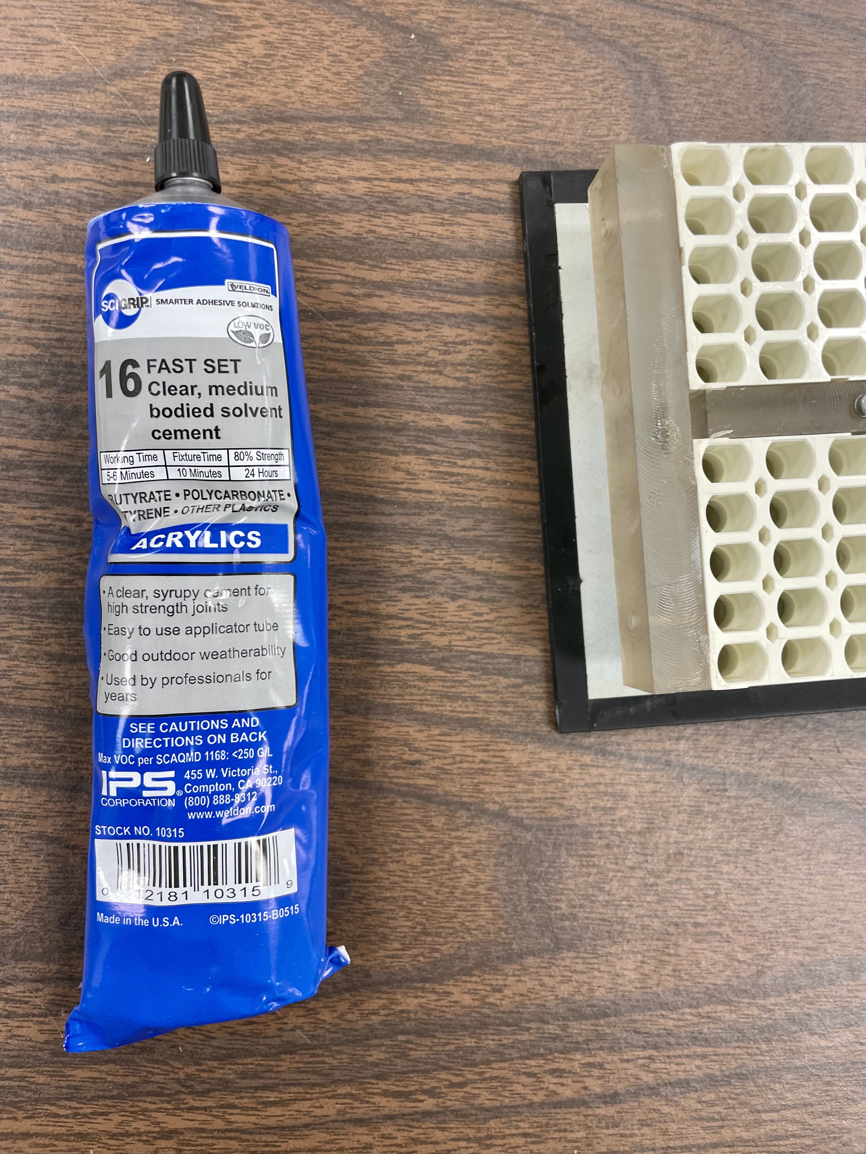
I had been waiting for a plastic glue, to affix the Lucite to the Nylon honeycomb, plus a rubber lip that would slide of the side of the PCB and fit into the steel U channels fasted to the Lucite blocks. When they finally arrived it was time to do the last bits of assembly. The glue-up was straightforward, held in place by a clamp until it dried. The rubber only needs to be cut to length and slid onto the PCB edge.

Glued but needs 24 hours to reach 80% of final strength

Thursday, July 7, 2022

Accelerating the sludge removal from the 1053 Console Printer

APPLIED NEW CLEANING METHOD

A fellow restorer has recommended that I soak the typewriter in a warmed bath of Simple Green, which won't damage the motor or solenoid enamel coatings. I picked up a large tub, aquarium heater and high capacity pump to agitate the solution, mixed up some cleaning solution and dumped the typewriter into it to see how it worked.

I had warmed the solution to 93 F, the max that my heater can be set to, before inserting the typewriter into the bath and switching on the pump. The water from the tap was already at 90 F and the sun on the solution pushed it up over 100 so I really didn't need the heater. 

Bathing in Simple Green with circulation pump

I left the mechanism submerged for a few hours before I pulled it out and disposed of the soiled solution. I carefully checked the bath for small springs or other parts before tossing it out, just to be sure that the water circulation didn't dislodge anything. 

The 1053 mechanism from the 1130 I am currently restoring was first into the bath. When it was removed, I tried to operate a number of mechanisms that had been frozen or sluggish before, such as the print cycle clutch and the carrier tabbing to the right. 

They moved! It does seem to work, in spite of its gentleness. I set up a table and a production line to soak my three selectric mechanisms - two 1053 console printers from 1130 systems and a Datel Model 30 terminal, which was sold as an alternative to the IBM 2741 terminal. Both of those are full typewriters that communicate over telecom lines, typically they were used as timesharing terminals. 

Mechanisms waiting their turn for the solvent bath

The two 1053 printers aren't yet perfect, but with quite a bit of grease removal I should have no problem getting them to 100% functionality. The one from the 1130 I am currently restoring was missing the rotate tape but I already had a new spare tape of the correct size. 

SELECTRIC CARRIER - SOME BACKGROUND READING

The carrier is an assembly that slides left or right on a round rail in the front and slides across a flat plate at the rear. Near that flat plate are two toothed racks. Levers on that back end produce a single step forward in a space operation, a single step backwards for a backspace, or latch the levers out of the way to allow the carrier to be pulled rightward until a projecting tab pin unlatches the lever to stop the carrier at an intended tab stop. 

The round rail in the front will rotate once for a print cycle, which imparts the motion to slam the typeball forward to that a spot on the ball strikes the platen through the ribbon and paper. Thus the lowest level on the carrier is a platform that pivots front and back to move the ball to the platen.

The type ball sits on a pivoting front to back subassembly which produces the tilt. That is, it leans the ball forward or back to put one of the four bands around the ball in position to strike the ribbon and paper. This is the top level of the stack - lowest pivot platform, middle rotation wheel and then the upper tilt assembly. 

In the middle on that pivoting subassembly is a wheel which rotates to move the ball so that from the top it is turning clockwise or counterclockwise. This wheel can be moved to one of five positions in either direction, thus there are 11 discrete rotations of the ball that are selected. Combining 11 rotations and 4 tilts gives 44 selectable characters. 

The wheel can be moved more dramatically to rotate the ball an entire 180 degrees, making use of a second hemisphere. This is a shift operation. Printing a character by picking which of the 44 on a hemisphere to slam into the ribbon is done during a single print cycle. However, to shift or move to the other hemisphere needs its own cycle prior to the actual printing of a character on the other side. 

Tilt and rotate are selected by tightening or loosening metal bands that run over pulleys on the left and right side of the typewriter, while being fastened to the carrier at each end. Thus, if a pulley on a lever is bent away from or toward the center, the effect is to move the tilt or rotate part in the carrier. One end of each band is fixed to the carrier itself, the other end of the band is hooked to the wheel (for rotate) or to the pivoting subassembly (for tilt). 

Early in a print cycle (one rotation of the print shaft), the tilting and rotating take place. The ball spins and tilts to position the character properly. Later in the print cycle, it slams the ball forward to strike the ribbon and paper. 

Additionally, parts move the ribbon up into position, leaving it down and out of the way so the typist can read the prior characters easily until it is needed during the act of printing the next character. On the 1053, the ribbon lift mechanism has two settings, controlled by yet another band. A plastic band is tightened or loosened by solenoids on the side of the machine to control how much the ribbon is lifted when it moves up for a print operation. Using a ribbon that is divided down its length with red and black inked halves, the variable lift can select the color that will be used for the typed character. 

A few other parts are here as well, adjusting the striking force for when carbon paper and multi part forms are used on the typewriter. All of these parts must be cleaned and move freely to have the typewriter work properly.

CORROSION CONCERN

I do see some corrosion on the rails that the carrier moves along. It does not seem to affect its operation but I won't know fully until I get everything freed up and working well. It is possible that these will need to be resurfaced or replaced. They are common to ordinary Selectric I typewriters thus spares can be found if needed. Look closely at the rough surface. Perhaps the bearings that slide along this are also galled internally. 

Worrisome corrosion on the front rail for the carrier

Wednesday, July 6, 2022

Taking advantage of cleaning process to handle all my Selectric printer mechanisms

SETUP OF THE BATH, HEATER, PUMP AND SOLUTION IS AN OPPORTUNITY

Since I will have prepared everything to dunk the 1053 printer from the machine I am restoring and remove stale lubricants, it is an opportunity to clean the other two mechanisms that I have. My own 1130 has a 1053 which is in much better shape than the restoration printer, but could still use a bit more cleaning. 

In addition to those, I own a Datel 30 terminal, a product built to compete with IBM's 2741 terminal. These use the Selectric typewriter mechanism and were connected over telecommunications lines to a remote computer to support timesharing and terminal access. Just as the 1053 makes use of solenoids and microswitches, these other terminals use them as well. 

While the 1053 is an output only device - a console printer - the 2741 and Datel 30 are both input and output, having keyboards as well as the typewriter output mechanism. This is even more firmly frozen than the 1053 printer, thus needs a deep bath before I can get to work on it. It appears to be in good shape with intact metal ribbons and other parts. 

Underside of the mechanism

Top view of the mechanism

1053 Console Printer - not an ordinary typewriter Selectric element (ball)

STRUCTURE OF A SELECTRIC TYPE ELEMENT 

The familiar 'golf ball' element from the Selectric typewriters is a metallic appearing ball that snaps onto the mechanism of the typewriter. Changing elements allows the typewriter to print with different fonts and special characters. This ball is actually constructed of nylon, colored to look metallic as IBM believed that a plastic appearance would be taken as a sign of cheap construction. 

The ball is a partial sphere, injected molded as two almost hemispheres then fused into the ball shape. Around the lower 'skirt' are teeth which allow the typewriter mechanism to lock the ball into precisely the right rotary position when typing a character. 

The center of the ball is the attachment point to the typewriter mechanism. One hemisphere is the regular or unshifted side, representing the lower character on keycaps, while the other hemisphere is reached by using the Shift key and thus will type the upper character on keycaps where there are two symbols. For letters, the two sides had lower case and upper case letters. Other keys had two symbols, e.g. the key with 1 on the unshifted hemisphere and the ! on the shifted side. 

A hemisphere is divided into 11 rotary positions from one edge to the other, these are termed rotations of +5, +4, +3, +2, +1, 0, -1, -2, -3, -4, and -5. The face is also divided into four rings that run left to right. The ball can be tilted to the 0, 1, 2 or 3 tilt level (T-0, T-1, T-2 and T-1,2), in addition to its rotation to one of 11 rotary positions. 

This combination of tilt and rotate places one of 44 positions on the hemisphere directly facing the ribbon in front of the paper and platen. You can see the raised letters on the element at each of these 44 positions. Fusing the two sides into a sphere provides the full 88 characters available on a type element. 

Note that this is for the original Selectric mechanism, sometimes called Selectric 1 to distinguish it from later versions that had balls with 96 elements in total for the Selectric 2, Selectric 3 and other families that came later. The 1053 is an original Selectric family member and uses the 88 character elements. 

TYPEWRITER ELEMENTS USE CORRESPONDENCE CODING

The ordinary Selectric typewriters of that era assigned the characters on the keyboard to various positions on the type element in a fixed way. That is, if you swapped a Letter Gothic element for a Prestige element, the same character was at the same relative location on the ball, although its typography was different to produce the different font type. 

On the correspondence elements, some sample characters and their positions were:

  • A   T2,  R -2
  • Z   T0,  R  0
  • 0   T0,  R +4
  • /    T3,  R -1

MAINFRAME AND TERMINALS HAVE ALTERNATIVE PTTC/BCD CODING

An older encoding system was used to encode characters for typing back in the 1401 computer era, where the 1050 terminal system initially used the Selectric mechanisms. These machines stored characters in Binary Coded Decimal (BCD) and on paper tape in PTTC code. The type elements produced for those older systems had the characters assigned in different locations on the ball. 

The 360 and all the Selectric mechanisms in the 1050 series (1052 and 1053) used the BCD encoding. IBM produced some Selectric based terminals, for example the 2741, that could be wired to either coding scheme. Famously, users running the APL language on a 2741 had to know which encoding the terminal was wired for, in order to install the proper version of the type element. These were the 987 and the 988 elements, for correspondence or BCD encoding respectively.

The same characters in the short list for correspondence are on the BCD ball at:

  • A   T3,  R -5
  • Z   T1,  R +4
  • 0    T0,  R  0
  • /     T1,  R -5
We can therefore see that the ball in its home position of zero tilt and zero rotate would produce a Z on the correspondence element and a 0 on a BCD element. 

THE TYPEBALL ON AN 1130 AND A S/360 CONSOLE

IBM Selectric Type Elements have a three digit code stamped on the nylon ball just under the lever on the top which identifies the font on the ball as well as whether it is correspondence or BCD. The ball on the 1130 is a 969 - "1131 & 1800 SYSTEM UC~UC" and the 360 console uses a 952 - "360 EXTENDED BCD"

Monday, July 4, 2022

Double checked the 1053 emulator before attachment to IBM 1130

CAREFULLY CHECKING THE 1053 EMULATOR BEFORE USE

I designed and built an emulator to plug into the 1130 for when the console printer is not operational. It is shared on Github as https://github.com/cclaunch/PC1053 which I am updating based on this checkout and subsequent testing with the computer.

I am not sure if this had been plugged into my IBM 1130, it may only have completed checkout with a test driver subproject. Any errors in my implementation are likely mirrored in the test driver, thus this warranted some careful validation before I will turn on power on the 1130. 

The first step was to verify from the 1130 ALDs that the connections on the SMS paddle cards are the signals I believed they were. I then beeped out these to the emulator to be sure I wired them to the intended pin of the Arduino or the intended terminal of the relay boards.

This design makes use of the open collector gates that IBM uses in the 1130 to drive the solenoids of the real 1053. These work fine with the pullup resistors built into the Arduino, thus I can directly hook these inputs to the Mega2560. 

I fired up the emulator without hooking it to the 1130. This let me inject various signals as if the 1130 were emitting them by simply tying that SMS paddle pin to ground. I verified that the relays and the signals they connect were in the proper idle state, including reporting that paper was now in the typewriter. 

All appears good, so it was time to connect this to the live 1130 system and begin debugging both my emulator and the device controller circuits inside the 1130. 

HOOKUP AND USE WITH THE 1130 - SOME COMPLICATIONS

The 1053 connects to the 1130 with three SMS paddle cards, two for signals and one for power. SMS cards have 13 fingers on the end of a phenolic printed board, labeled A through R from left to right. IBM named the two signal connectors PF1 and PF2, while the power connector is called PP1. 

With three otherwise identical SMS sockets, it would be important to get the proper paddle cards in the proper sockets. This is nothing unusual - nothing blocks putting an SMS logic card into a 1401 system in the wrong place, just as nothing stops someone from putting an SLT card in the wrong slot of a compartment on the 1130. 

However, it appears someone was unduly concerned, as IBM took extraordinary steps to protect against inadvertent misconnection. The power paddle card fits into a bank of sockets for power delivery that has a heavy metal bar spanning the H finger position of all sockets. Thus, the paddle cards for power have to notch out the card where the H finger would sit so that it can slide in, otherwise it is mechanically blocked. 

1053 power paddle card with notch 

I can understand a bit why the power sockets need protection - there is 230VAC, 115VAC, 48VDC and 12VDC delivered across those fingers which would be a bad thing to deliver to logic cards or the signal paddle cards. However, IBM didn't stop there. They could have put notches in different positions of the two paddle cards and their corresponding sockets, but they did not. Instead, they converted one of the two paddle cards to a hanging SMS socket. 

That spoils the purity of the SMS based signal connections. These are used for various peripherals - the 1053 printer, the 1134 and 1055 paper tape devices and the 1627 plotter. The block for these signal connections either has sockets installed or blank spacers for devices that are not configured on a particular system. The cards push into the block from the front and the sockets or spacers are all held down by metal rails which are bolted together at the ends. 

Except . . . the 1053 signals are a pair of reversed connectors - one socket and one paddle card on the CPU side and one paddle card plus one hanging socket for the 1053 side. One can't simply pull the socket off the card, instead you must remove the metal bars, take apart all the sockets and spaces, thus freeing the socket that is attached to the 1053. 

Signal cables PF1 below and PF2 above

Since these two blocks for SMS connections are down inside the bowels of the machine, behind the built in disk drive and just behind power supplies, you must swing out the logic gates and crawl inside the machine to connect or remove these cards. 

I now have an answer to my question of whether I had ever connected the 1053 Emulator to my 1130 system. I could not as I built the emulator with two paddle cards for signals and a regular power paddle card. No notch in the power card. No socket on the PF2 signal line, just a paddle card. 

Emulator with paddle cards for both PF1 and PF2

MAKING CORRECTIONS TO THE EMULATOR TO PERMIT CONNECTION TO THE 1130

I used a hacksaw and cutters to open a notch where the H finger was on the power paddle card, allowing it to fit into the 1130's SMS power connector block with its blocking metal bar. 

I found my spare SMS socket, one designed to take push on clips rather than wire wrap or solder. It took quite a bit of heat and technique to solder wires to those wide bars but I completed that, then soldered those wires into the paddle card for PF2. It is a bit clunky, but I can insulate and tie up the paddle card part and use the socket for the connection to the 1130's card. 

If this were going to be a regular peripheral connected to 1130 systems I would hunt down a proper hanging SMS connector and wire it up to the emulator, doing away with the paddle card and funny socket extender. However, I see this as a device to be used for intervals where the 1053 itself is off the machine being serviced, to be removed once the console typewriter is back in service. 

Work on securing light panel with new mounting hardware

 NEW LIGHT PANEL ATTACHMENT BUILT

The IBM designed light mechanism behind the display panel above the 1053 makes use of a nylon honeycomb (the same was used to hold the display panel lights on the IBM 1401 computer), with bulbs press fit into each cell of the honeycomb. The bulb is inserted into a nylon holder first, with the wire leads threaded through holes in the holder and bent to each side. Pins press into the rear of the holder, making contact with the lamp wire and completing the circuit.

The other ends of the two pins for each light are on small wide boards that support either 8 or 16 lights each. On the board is an SCR with a fixed pin, plus another pin on flexible pigtail wire. The rear of the board has a pin that is connected to signal wires from the 1130 circuitry. On the left or right side of the board are thick power wires that bring the 7.25VAC, ground and lamp test power.

The lights are packed closely together, with just 3/4" between each vertical row of lamps and thus the boards are 3/4" apart. The lights are 3/8" apart left to right on the boards. This gives little clearance to reach in among the six rows of boards and 16 to 32 pins that have to be pressed into the 8 to 16 lamp holders that are fitted in the honeycomb. 

An alternate method is to remove all the lamps, press them on the pins, then try to swing the entire board in place and press all 8 or 16 holders in the honeycomb. Once again, very little clearance exists. 

This is a very frustrating and tedious process that has to be done whenever a light bulb has burned out, in order to replace it. Further, on transport the lamp holders tend to work out of the honeycomb leaving the boards and lamps dangling in a huge mess of about 150 lamps total. 

As one final burden for owners of old 1130 systems, the honeycombs are glued to Lucite blocks on the left and right that were threaded to hold the honeycomb and front panel in place. The glue between the lucite blocks and the nylon honeycomb almost always has failed, leaving the front panel wobbling or fallen out. Sometimes the honeycomb, which is an assembly of smaller blocks of honeycomb, comes apart as well. 

I designed a new method of attaching the lights to the honeycomb and the 1130 circuitry to greatly reduce the burden of replacing bulbs. I created a single large PCB that fits across the back of the entire honeycomb, supporting all of the lamps on one board. This has surface mount SCRs, connectors and other parts installed to completely replace the small wide boards and nylon holders used by IBM. 

Up until now, I had this board, with all the lamps installed, propped into place behind the honeycomb with soft foam keeping it from falling back. It really was not supported or mounted, a problem that is worse with the 1130 I am currently restoring as it has no rear door for the display structure onto which foam would press. 

I developed a mounting system with two bits of steel channel brackets, threaded for a thumbscrew. These fit from the side, going over the Lucite holder that is glued to the honeycomb and screwed into the display structure. The thumbscrew tightens against the Lucite to hold the bracket in place. 

Soft rubber channel will be fitted along the left and right edges of my PCB and is secured under the lip of the channel, holding the board in place behind the honeycomb. The rubber doesn't arrive until the weekend and I also must wait for the special glue that binds the Lucite and Nylon together

LIGHTS CURRENTLY OUT OF THE 1130

There had been a flaw in the panel built by the prior restorer of this 1130 using my PCB and design. One of the SCRs had a lead that was not soldered onto the board, thus it neither lighted with a signal from the 1130 nor with the lamp test switch. I took the board out to repair that last week and now reassembled the bulbs onto the board and will install it using my new mounting method as soon as the last items arrive in the mail.

Friday, July 1, 2022

Worked on some mechanical/structural details of the IBM 1130 under restoration

MISSING REAR DOOR LATCH HANDLE

The rear door of the 1130 that pivots from the left rear corner and is the door most often opened other than the front door of the disk drive. It had a handle that was pushed down against spring tension to release the door, allowing it to swing up. The inner part of the latch including the springs are still mounted, but the outer handle that people grab is missing.

I sorted out a method to build a simple latch handle and mount it to return the door to full operation. The inner mechanism had two holes that the outer handle had been press fit into. I found that I could screw bolts into those holes to secure a new handle. I choose a 1" x 1" by 1 7/8" wide block of wood as the new handle, because I could easily countersink the holes for the bolts and cut this to size. 

Once I am certain that it works properly I will spray paint this a suitable color to match the 1130 doors, then put the rear door onto the computer. 

SECURING AND SERVICING MY IMPROVED INCANDESCENT LIGHT SYSTEM

The cumbersome and failure prone system that implements the roughly 150 lamps for the display panel is a thorn in the side of every 1130 owner. I designed and implemented an alternative that puts all the lamps on a single large PCB that fits right behind the honeycomb housing where the original individual lamp holders were plugged in. 

That PCB did not have a good firm attachment method - I pushed it into place but it would slide out during transportation so I knew that I had to solve that eventually. The prior restorer of this computer built one of my PCBs since the lights had fallen apart on their system also. 

I think I have a good mounting system for this and began to build the two side brackets that will clamp onto the honeycomb assembly and its mounts. I am using two U channel brackets, drilling and tapping for a thumbscrew to lock the clamp into position. As soon as I get this built and test its fit, I can complete brackets to hold the board onto the 1130 I am restoring. I would also build a set for my own 1130 and install them there, of course.