Friday, July 27, 2018

Modification to allow use of ASR 33 paper tape reader with PDP 8 clone (SBC 6120)

VINTAGE COMPUTER FESTIVAL EXHIBITION PREPARATION

I was exchanging emails with a DEC computer collector and mentioned that the SBC 6120 didn't have the signal output to switch the Reader Run Control relay board in the ASR 33. Without the signal, the motor of the punch tape reader runs at full 110 baud speed which is too fast for programs in a DEC minicomputer to keep up.

To avoid overruns, the serial board in the PDP 8 will switch on and off a signal driven by software. The software is interrupted when the serial board has received a character into its buffer and can interrogate a flag indicating the data is ready for transfer. A program will fetch the character and then issue a command to reset the flag.

When the flag is on, the Reader Run Control relay is switched off pausing the paper tape reader motor. After the software clears the flag, the relay turns back on and the paper tape reader advances to the next character.

I looked over the schematic of the SBC 6120 and examined the data sheet of the Harris 6402 UART chip it uses for serial data. The clone uses the Data Ready pin from the 6402 as the flag that is visible to software, and the command to clear the flag toggles the Data Ready Reset pin.

Pins 18 and 19 of the Harris 6402 chip

Schematic portion with 6402 UART chip wiring
Thus, I can tack a wire on the 6402 to watch the Data Ready signal, invert its state and convert to an RS 232 level signal to drive the relay coil of the Reader Run Control board inside the teletype. I will have to scramble to build the circuitry and do the modifications, then test this to see if I can successfully read in programs from paper tape when running on the SBC 6120. 


Monday, July 23, 2018

Fixed SBC6120, made duplicate paper tapes, and know cause of linefeed issue on ASR 33 teletype

VINTAGE COMPUTER FESTIVAL EXHIBITION PREPARATION

I hooked up the Altairduino to the teletype and successfully brought up 4K Basic, loaded a program to print prime numbers from paper tape, typed RUN and saw it run correctly. Still no linefeed function but otherwise it works well.

I switched over to the PDP-8 clone (SBC 6120) but didn't have good results. The output on the teletype was garbled and the machine itself was balky. I opened up to see what was wrong and quickly discovered a loose wire to my UART configuration switch.

I do get some oddly garbled initial text from the SBC 6120 itself, but the output from OS/8 itself is good. I did some testing, including booting OS/8, loading PFOCAL and running the focal program HANOI to play Towers of Hanoi. All looks good here.

I did a test to see if the SBC 6120, as a realistic clone of a PDP-8, would suffer from the same problem reading in paper tape. On a real PDP-8, the IO card buffer gets overrun by the incoming characters from paper tape. To resolve this, the PDP-8 has a modification for the ASR 33 which starts and stops the tape reader motor under program control.

Alas, this requires access to the control signals from the PDP-8 IO card, but all that is available on the SBC 6120 is RX and TX lines. Therefore, I see no way to control the teletype paper tape speed to avoid the buffer overrun problem. My demonstrations with the PDP-8 clone won't use paper tape input. 

I chose to punch a second set of tapes for the two longer programs, Hangman and TicTacToe4K, because they don't depend on the linefeed function which is not working yet. I completed these, which gives me two good tapes per demo program. I can always punch more at VCF if that is needed.

To produce the additional copies, I put the ASR 33 in Local mode, stuck the existing tape in the reader and pushed On for the paper tape punch. Once I turned the tape reader lever to Start, it was reading and copying the input tape onto the output tape. 

ASR 33 TELETYPE REPAIR

The problem I faced today was failure of the printer to advance when the LineFeed button or received character is present. I can make it work if I partially depress the feed pawl, thus I will be looking for missing or broken parts. I had to remove the cover of the machine to see into the mechanism and begin the debugging.

I opened up and began inspecting. Nothing appeared missing or damaged, although I did notice some flaking remnants of plastic of some type on a bracket associated with Line Feed. I pulled off the little chunk that was left and looked to see if a bigger piece had fallen into the mechanism and jammed something. Nothing obvious here. The diagram I had describing the workings of the line feed function didn't show the item in question.

Wonders of the internet! Somebody had the exact same issues as me, and their description pointed to a bit of plastic that must be in place for Line Feed to work. http://www.foxdata.com/blog/line-feed-not-working/ is where I found the writeup. This exactly matched my situation.

When I am through with VCF West, I will be visiting RTTY Electronics, Paul Cembura, for parts for the model 15 and also for the correct bit for this machine. In the meantime, I will fabricate some workaround just as he did. I will be guessing about the offset necessary, but hopefully it is not too critical. My first three tries were off, the last unfortunately lead to LF after every printed character.

I then put in an hour poring over the parts list for the model 33, trying to find the plastic part or even the parts near it, all to no avail. Since there are two other model 33 teletypes at Marc's home, there should be a part he can grab and model a replacement on. I do have a week and a half to search the parts list hoping to locate the official part number. 

Sunday, July 22, 2018

BaudotRSS program fixed and ready to drive model 15; paper tapes punched to drive ASR 33 demos

VINTAGE COMPUTER FESTIVAL EXHIBITION PREPARATION

I wired up a USB link to true RS232 to allow me to directly drive the ASR 33 from the PC, with the intent of producing punched tapes for the upcoming demonstrations at VCF. With this working properly, I attached to the teletype and ran a terminal program which read a text file and sent each line to the teletype for punching.

First to run was a short basic program Prime to list prime numbers. It punched well and seemed to read back just fine. The extremely old paper tape I have on the machine is challenging to force into the punch. I spent some time fighting with the tape and punch until I was ready to punch out the other demo tapes.

Next up was Hangman, a relatively long program. I spent a miserable 20 minutes with the punch repeatedly stopping halfway through the program when the shoddy quality tape that I have on the machine would jam. Each time, I have to rethread the tape and start over. I took a mental health break.

I then remembered that I had bought some paper tape rolls many years ago when I was building a paper tape punch for my IBM 1130 replica. I found the box and grabbed one of the rolls. I threaded it into the ASR 33 and was back in business. I punched out Hangman, TicTacToe4K and another copy of the Prime program.

I did have to hold the spool of blank tape and feed it out in a loop, since there seems to be too much drag when the roll is sitting in the teletype feed slot. I will look into this later, perhaps it just requires some cleaning and waxing of the surfaces to reduce friction.

Hangman, TicTacToe4K and Prime programs on paper tape
The old paper in the teletype is as bad as the paper tape stock - frequently jamming up and blocking the line feed from advancing the paper. I did buy some new paper rolls, but also plan to unroll the old paper. It is two copy paper, although whatever chemical was intended to act as carbon paper has long since evaporated.

I unspooled the entire roll onto the floor and then rolled up each of the two copies separately to produce two 'new' rolls. If these feed well enough as single copies, they are preferable to use at the show. They are the standard teletype light yellow color and the top copy has Western Union Telex printed along the left edge for extra authenticity.

Unspooled two ply paper roll
After a wonderful half hour spent separating and rolling up the outer ply, I had one roll of WU Telex paper ready to install in the machine. I got it lined up and discovered that somehow my line feed (LF) had stopped working. The printer won't advance the paper when an LF arrives!

Now I have something broken to repair again. Very disheartening. I have family obligations which will keep me from doing any work from the 24th to the 31st of this month. With VCF West loading on the afternoon of August 3rd, I only have three full and one partial day left to deal with this.

Bummed out and having a huge pile of paper on the den floor, I had to roll up the second play to make into a usable paper roll. That took about 30 minutes and took my mind off the treachery of the ASR 33 printer.

Second ply in a heap on the floor
The problem with the line feed seems to be something up on the left side of the platen. I suspect that a spring was dislodged by the crappy two-ply paper which was jamming up earlier, or a part broke. The feed pawl (see below) doesn't move when a LF is commanded, but if I push the pawl down a bit there is a zone where it will reliably jump and pull the platen one line up.

Line Feed mechanism
The feed pawl seems to snap back up, so I can rule out loss of its spring. I will be looking at the line feed linkage in more detail, after I remove the covers from the unit. This will have to wait until tomorrow. 

I had some problems with conflicting Python versions on my laptop, which affected the BaudotRSS program which will drive my model 15 teletype. I did a clean install of Python 2.7 on a desktop machine I use for amateur radio and HP 1000 disk emulation, installing all the packages needed by the program.

Everything appears to work perfectly, based on log output and the blinking lights on my teletype interface box. Before VCF West I will have to bring the entire desktop PC over to the model 15, or bring the model 15 over here, and run a final test.

I took some acrylic square rods and glued them to the SBC 6120 panel to fit it to the wooden box I recently bought. This provides a nice case for use during VCF West.

PDP-8 clone

Friday, July 20, 2018

My model 15 teletype working great, plus prep for VCF West exhibition

VINTAGE COMPUTER FESTIVAL EXHIBITION PREPARATION

I updated the configuration file for the BaudotRSS program that will drive the model 15 teletype at the festival. It will allow us to print news or weather reports, producing that wonderful newsroom sound and some output that can be handed to attendees.

The program was set up by default to assume that the teletype does a linefeed after every carriage return, but that is not true of our model 15s. I changed the code to interject a LF after each return. The other change was to specify weather reports for Mountain View where the festival takes place, and add some interesting news sources to print. 

I moved my ASR 33 into the garage, mounted it on its stand and loaded blank paper tape in preparation for punching out the demo programs. I couldn't figure out how to punch leader - an ASCII null character - since there was no visible key on the keyboard for it.

I decided that I could switch to Line mode with nothing wired up, which causes the machine to see a continual stream of null characters and thus punch them as leader. Now I am ready to punch my demo tapes, hooking my PC to the teletype with a USB to serial connector and MAX3232 voltage converter.

I bought a wooden cabinet that was a reasonable fit, although not perfect, for the SBC 6120 computer. Acrylic blocks glued to the rear of the computer front panel will hold it in place in the opening of the box and allow the power cord and RS232 cables to run out the bottom.

Bob Rosenbloom will be bringing in a non-working ASR 33 mechanism to set on the desktop to let people look inside and see how the machine is constructed.

MODEL 15 TELETYPE RESTORATIONS

This morning I identified some areas that might be causing the failure of the ribbon of my model 15 to advance properly. The first thing I spotted in the diagrams was a 'ribbon lockout lever' which is probably activated. Sigh.

After arriving at Marc's I spent time on two aspects of my teletype, the ribbon mechanism and the selector mechanism. Typing does not show up on the paper and the ribbon does not advance. The selector vanes move a bit sluggishly, vane five is not deflecting to its end positions and there are erratic mistyping results of the vanes not following the input data stream.

First up, I lubricated and exercised the selector mechanism and vanes until they felt free and didn't appear to stick at all. Then I was ready to hook up the teletype to my computer interface box and begin some testing. That is, after I attended to the nonfunctioning ribbon.

I looked closely at the printer. Yes, indeedy, my ribbon lock lever was set. I unlocked the mechanism and then turned on the teletype and interface. After a bit of adjustment of the 'range finder' which determines the spot during each bit cell that the condition is sensed, my machine began to type flawlessly.

Alas, the ribbon was not winding, but it is at least printing nicely when I manually shift the ribbon a bit. Once I attend to this last part of the task, this model 15 will be ready for its role printing at VCF West.

I tried out the weather forecast mode and indeed it printed the forecast for Mountain View, California, the site of the festival. Once I have the ribbon advance working properly I can try out the newsfeed mechanism.
Weather report printed on old paper
After quite a bit of lubrication and a good 30 minutes of turning of the most stucky of the ribbon reel gears, I got everything freed up and looking good. The machine was reassembled and went right into service, typing flawlessly with the new ribbon and new paper.

Model 15 as it will sit at VCF West
Something is not right about the newsfeed option - presumably this will print the top stories from selected RSS feeds - since the program complained that there were no new stories. Ken Shirriff helped investigate the malfunction and it appears that the way I have Python 2.7 and Python 3 installed on my laptop is causing some conflicts and impacting the program execution.

I plan to install just Python 2.7 on a desktop computer I own, giving a pure environment for the BaudotRSS program. If that seems to work without a teletype attached, I can do a final verification at Marc's house the next time I am there. 

Thursday, July 19, 2018

Finished repair of ASR 33 punch, worked on model 15s, and prepared for exhibition at VCF West

ASR 33 TELETYPE RESTORATION

Wednesday night, the eBay perforator arrived and I disassembled it to have the replacement parts for my ASR 33 tape punch. This arm with the teeth has a spring that attaches - the choice of tooth determines the tension on the paper tape as the punch operates.

The part that will replace my broken one
The part after removal from the spare perforator
I removed the broken part from the ASR 33 perforator and slid on the replacement part. The last step in restoring this unit was completed when I used a spring hook to pull the spring up and fasten it on one of the teeth.

Broken arm on the ASR 33 perforator, before removal and replacement
The new arm is in place now and I can begin to punch tapes necessary for the exhibition at VCF West. 

MODEL 15 TELETYPE RESTORATIONS

After studying the manuals and thinking about the symptoms of my model 15 (printer doesn't move print or function bails), I have zeroed in on the section I believe is frozen in place and needs some work.

Most likely mechanism causing symptoms - Clutch Throwout Lever and Stop Arm
There is a lever which rotates to engage and stop the clutch for the two cams which drive the print and function bail movements. A cam on the selector mechanism pushes the Cam Arm, causing the Clutch Throwout Lever to rotate on its axis, allowing the spring to push the clutch teeth together. This rotates the two cams that push the bails.

I confirmed that the driving clutch member is not sliding on the main axle and meshing. It took 90 minutes of manipulation of the newly oiled member before it would slide into mesh and pop back crisply. Hundreds of movements of the member, using a screwdriver as a prybar with gradually lighter pressure once it began to behave properly.

I took the carriage assembly off to work on the main shaft and other linkages. When I reinstalled it, I somehow pinched the strap that pulls the carrier back to the left. This strap is wrapped around a circular spring assembly and its other end is clipped to the right side of the carrier.

Marc repaired it, making a slightly shorter strap by opening the clamped metal, looping the remaining strap through the end hook and reclamping. It was installed and I once again have carrier return on the printer.

I hand rotated the main shaft and set up various baudot code patterns on the vanes. For example, I set them to SPACE, SPACE, SPACE, MARK, SPACE which is a CR command, then watched the mechanism trigger the return and it complete successfully.

I then triggered LF and verified the platen advanced one line. I triggered 'Space' and saw the carrier move one column to the right. Figures and Letters caused the entire platen to move up and down so the selected half of the typebar will strike the platen.

The computer interface then drove a pattern of alternating R and Y characters, a classic pattern used to adjust teletype reception. The results weren't perfect, although I had a decent number of R and Y strikes, there were plenty of miss-selected characters. I shot some slow motion video to examine further. It appears I have a slow vane number 5, sometimes settling in an intermediate position between MARK and SPACE - which is invalid.

I put a new ribbon on the printer but something is wrong with the ribbon advance mechanism as it isn't moving. I will review the documentation and then work on my model 15 some more tomorrow morning.

Marc worked a bit on the "Bob Erickson" model 15. First up was the need to adjust the speed to 45.45 baud, since this particular printer uses a governor to control motor speed. He hooked up an oscilloscope to the keyboard circuit, drove it with a power supply, and watched as he typed various characters on the keyboard.

He adjusted the motor speed until the bit cells took up exactly 22 ms. We then connected the computer interface and printed various patterns until it was working perfectly. When the interface listed its menu of choices, such as news stories or weather reports, we tried to select a choice by pressing a key.

The computer interface registered the wrong character - when Marc pushed W the interface saw a Z. A quick check with the oscilloscope confirmed that the keyboard is not encoding correctly. The contacts were quite dirty. After time spent cleaning the contacts and checking the results, we had the keyboard working well.

Unfortunately, I we ran out of time and couldn't continue with the computer interface testing. Next session, we plan to hook the keyboard and printer in a local loop, exercise the Erickson machine and hopefully have it ready to use at VCF if I can't get my unit working in time.

PREPARATION FOR VCF WEST EXHIBITION OF TELETYPES

With my paper tape punch working correctly, I hooked up the USB to serial module through the MAX3232 board to drive the teletype. Using a terminal program that will feed text files to the teletype, I simultaneously listed and punched a few basic programs to use as demonstrations at the festival. These will work with the Altair 8800 clone.

I am sketching out ideas for scripts to use at the festival, allowing my helpers to give the same experience when I am not at the booth. These are essentially all examples of booting 4K Micro-Soft basic and loading the paper tape for a particular game or demo. In most cases, the attendees can interact with the programs using the teletype.

I have Adventure somewhere on the PDP 8 clone, along with OS/8, so I just need to script out the startup procedures and give them some aids to help attendees get through some early challenges in the game.

I also need to script out the method of switching the teletype between the two clone computers - it is pretty straightforward but worth documenting just in case. There is no such switching necessary for the model 15 teletype and its connection to a PC, although I will script how to restart the BaudotRSS program if something goes wrong.

For the model 15 demo, I did some experimenting to find interesting RSS feeds that could be printed. I will test this tomorrow; hopefully having something interesting to type out. 

Tuesday, July 17, 2018

Cosmetic items added to ASR 33 and some work done on model 15 teletype

ASR 33 TELETYPE RESTORATION

Today I drove up to visit RTTY Electronics, the world's largest business providing teletype parts, service and refurbished machines. I picked up the missing pieces for my ASR 33:
  • Local/Off/Line switch knob
  • Platen knob
  • Faceplate (Teletype logo)
All parts now installed, plus I have a spare rubber cap for the hammer that slams the type wheel against the paper.

The remaining part I need to finish the restoration is the 'arm with bushing' that snapped off. This part is used to adjust the spring tension that is applied to drive paper tape through the punch. I bought a spare perforator on eBay but won't have that until Thursday. 

MODEL 15 TELETYPE RESTORATION

I visited Marc's basement today for a short time and reinstalled the functional bail rod and related mechanisms into my printer. After making adjustments per the Teletype manual, it was time to remount the type carriage and make some tests. 

Hand rotating the mechanism while manipulating the state of the selector magnet armature allowed me to key in various codes, to verify whether each appears to work properly before running the machine under motor power. I tried these codes:

  • 01110 to encode the letter C
  • 01000 to encode a line feed
  • 00010 to encode a carrier return
  • 00100 to encode a space
  • 00000 to encode a chatter null

I did indeed fix the spacing clutch, so the carrier stays at its current position. What I discovered is that my main clutch that should be moving the function and print bails back and forth is not engaging. That means no printing, no chatter, no functions, just a quietly turning main shaft and the vanes trying to select characters based on the incoming code. 

Sunday, July 15, 2018

Modified SBC 6120 to work correctly with ASR 33 teletype, as well as tested Altairduino to TTY link

PREPARATION FOR VCF WEST EXHIBITION OF TELETYPES

My replacement MAX3232 board arrived and I wired it up to allow me to connect it to either the Cypress 2102 based USB to serial module or the Altairduino serial port, This board features a male DB9 on the end, for connection to my cable, Telebyte and teletype. Fortunately, both the USB to serial module and the Altairduino will be properly configured for 110 baud with the proper character size and stop bit values. 

I constructed a cable from DB9 to DB25 to carry the true RS232 signals to the Telebyte 65 converter which drives 20ma current loops to and from the ASR 33. All I have to do is plug in a male DB9 to this cable and it will drive the teletype correctly when set to 110 baud, 7 bit, even parity and 2 stop bits.

The SBC 6120 computer has a male DB9 and is transmitting at 111.6 baud, but not yet with the proper configuration e.g. it currently emits 1 stop bit. I plan to modify the machine to work properly.

I discovered that this PDP 8 clone computer uses the Harris HD6402 UART chip which allows for selection of the serial format including stop bits. That means I can adjust the chip by bending out some pins and tacking them to +5 or ground to set up the configuration of the console serial port.

I first experimented with the USB to serial module to see the effect of various choices in serial port configuration, to determine what control bit setting to attain with the Harris UART. Next up, I modified the computer to operate with those settings, then gave it a try with the teletype.

The UART does not support MARK parity, which means that I need to use an data=7 to substitute the last bit for parity and then select parity=EVEN to lead me directly into stop=2. The teletype will see a start bit, 7 character bits, even parity and 2 stop bits.

That last character should always be MARK but I can't insure that. Since the teletype is not a smart device, it should not react to the incorrect parity bit. I used the USB to serial configured as 300-7-E-2 but the modification to the Cypress 2102 chip on the module causes it to actually run as 110-7-E-2 which is what I wanted.

I was able to send long strings of text, faster than the teletype can print, which showed up perfectly. The input from the ASR 33 keyboard shows up faithfully on the PUTTY screen. That tells me that this setting should work fine for the SBC 6120 as well.

I hooked up my new MAX2232 to the Altairduino and plugged the MAX into the connector for my teletype. Everything worked great. I put the computer into configuration mode, which prints a long menu of options, and it all came out flawlessly.

Altairduino configuration menu
The only problem I had is an inherent problem of the Altairduino code - the command for setting the serial port is 's' and the command to save a configuration is 'S'. Since ASR 33 only produces upper case letters, my keystroke asked to save a configuration when I had hoped to list out the serial port parameters.

The Altairduino is configured as 110-7-E-2 and works fine with the teletype. The reason that I had garbage typed but correct response with the unmodified SBC 6120 chip was that an incoming character of 7-M-2 simply appears to be a 8-N-1 character or a 7-N-1 with an idle interval before the next start bit.

The incoming characters to the printer are sent 8-N-1 and that means the next start bit arrives while the Teletype is still expecting a second stop bit. This gets the bit stream out of sync and causes garbage to type interspersed with some strings that accidentally line up properly.

The Harris 6204 UART chip has five pins that configure the serial port - CLS1, CLS2, PI, EPE and SBS. The normal mode for the SBC6120 sets these to request 1 start bit, 8 data bits, no parity and 1 stop bit. To work with my teletype, I need to have it set to 1 start bit, 7 data bits, even parity and 2 stop bits.
Harris UART chip at bottom
The only signals that switch value between normal and ASR 33 settings as CLS1 (pin 38), PI (pin 35) and SBS (pin 36). The PCB has CLS1 and PI wired to VCC and SBS wired to ground. To change this around, I need to bend those three pins outward so they don't fit into the socket, then tack on wires allowing me to connect them differently.

Pins 35, 36 and 38 bent outwards to isolate them from PCB
I can do a quick and dirty, wiring CLS1 and PI to ground, SBS to VCC, which permanently sets the SBC6120 to teletype mode. However, without too much extra work, I can add a miniature DPDT switch. This will allow me to switch between normal and teletype mode at the flick of a switch.

CLS1 and PI signals on blue wire, SBS signal on white wire
I popped the chip, bent the pins, tacked on the wires and soldered together the DPDT switch this evening. I put the switch into the 'teletype' mode and stuck the unit back into its case. It was late but I went out to perform the final test that night (the ASR 33 is in my car trunk and I test with an outdoor table behind the car).

Everything worked great! The SBC 6120 booted OS/8 and I did a directory listing. The paper ripped a bit and messed up the line feed in a couple of places but the ASR 33 is working great. 

PDP 8 clone running OS/8 doing directory listing on ASR 33
The model 33 related hardware for the VCF West exhibition is set now. I will script out a few demos for both the Altair clone and PDP 8 clone, including paper tape input. I still need to test whether the teletype reader will overrun either of the clones; if they do, I won't be able to run an all out paper tape demonstration. 

Friday, July 13, 2018

Progress on model 15 printer and other teletype news

ASR 33 TELETYPE RESTORATION

I need one replacement part for the paper tape punch on my teletype, but the spares part specialists at RTTY Electronics don't have one. I did see an eBay auction of a perforator, which is the tape punch unit from a model 33. The seller allowed me to make an offer and we agreed on a relatively low price which will give me the spare part I need. 

MODEL 15 TELETYPE RESTORATION

I began again to work on the model 15 printer, to free up the clutch trigger and stop for the mechanism that is spacing the carrier, since it is frozen and causes the carrier to drift steadily to the right margin. 

There is a rod that the function bar and other parts rotate around, including the trigger and stop levers for the spacing mechanism. Those two levers were frozen in place. I decided that I had to remove the rod from the printer to get access to the frozen levers. I had to remove some springs and detach the function mechanism which drives operations when the five code vanes match the code for a function such as CR.

Frozen levers down inside the printer mechanism
After removing the rod and related parts from the printer, we could move the lever slightly by striking it with a hammer. We removed the bolts holding the rod in its frame, then tried to drive it out of the parts to clean things up. We could get it to move about a millimeter in either direction with a fairly hefty hammer and wood blocks, but no more.

Rod with frozen levers, plus function plate above
We clamped the whole mechanism down, dripped in very fine clock escapement oil, and hammered the levers to make them rotate. At first it took a wood block and hammer, but after about 30 minutes we could move them by hand, albeit very painfully. These parts should rotate easily and snap back under spring tension. 

Main shaft visible with the function rod removed from machine
Ed Thelan took over, judiciously adding clock oil while relentlessly moving the levers over their range of motion until they were fully loosened. This took him about an hour of stubbornly twisting the parts. At this point, we had to end the workday but everything is ready to reinstall and after some adjustments, the printer unit should be working. 

Bob Erickson's model 15 is a governor model, whose motor speed is adjusted by the technician. We used a box to drive the unit with 60ma 120V at 45.45 baud but the text being printed was somewhat garbled. Today we decided to adjust the motor speed, since it must be the right speed to decode the incoming data stream. To our surprise, the motor didn't start at all when we plugged it in.

We discovered a broken wire, which was fixed, and another wire which was hanging on by its last strand. Now it works again. The workday ended, but our plan when we resume is to hook up the SEND contacts to the oscilloscope and adjust the motor speed until the bit cells are exactly 22 ms, which corresponds to 45.45 baud. After we know the speed is right, we can test the printer again. It may be sludgy and require some TLC, but perhaps it is simply a matter of adjusting the speed. 

Marc picked up the powder coated metal parts for his model 19 teletype - they look fantastic. We now have to put everything back together; 39 coated metal parts and the many hundreds of other parts that go inside. 

Thursday, July 12, 2018

Testing out Altairduino and SBC 6120 with the ASR 33 teletype

TESTING THE VCF WEST EXHIBITION CONNECTIONS

I set up my test rig outside, with the ASR 33, the Altairduino, the SBC6120, and various tools like a scope and power supply. I worked my way out from the Altairduino, identifying the output stream when I attempt to switch over to the serial line as the primary interface. Seeing which line produces proper 110 baud ASCII, I then connected through the various devices and cables until I had the Telebyte driving the teletype.

When I applied the switchover on the Altairduino, the teletype printed out the message requesting confirmation of the new settings. However, it did not recognize my input keystrokes. I would get 30 seconds of prompts and then the Altairduino switches back to its USB link for communications.

I next wired up my USB to serial device (based on CP6102 chip), again identifying which line was modulated as I typed input on PUTTY on the PC. Wiring all that through to the Telebyte, I was ready for the next test. This part worked flawlessly, with every character entered on the PC keyboard printing properly on the ASR 33 and each keystroke on the ASR 33 displayed properly on the PUTTY screen. 
Signals going through MAX3232 converter
The above test lets me know that I have a fully functional ASR 33 and any remaining difficulties are going to be with my two clone computers and the wiring to the Telebyte. Seeing perfect output from the Altairduino is an excellent sign, so the only issue to identify is why I was not seeing the keystrokes coming back. I can diagnose this with a PC to Altairduino link, both sides at 110 baud, until I find the problem. 

My final test was the SBC 6120, which has an RS 232 (TTL) interface that I believe I had set to 110 baud using the new slower TTL oscillator chip. Once again, I identified the modulated pin coming out of the SBC 6120 and wired it through to the Telebyte and the ASR 33. 

The results were not as positive as I had hoped. The teletype went into chattering mode, which happens when it receives start bits with ascii NULL following. When I pushed the keys on the teletype, it interrupted the chattering and tried to echo something back to the printer. 

I put the meter on the cable from the SBC 6120 and realized it was already RS 232 voltage levels and thus inverted. That explains the results I experienced. I can simply wire this replica right to the Telebyte input and it should work perfectly. 

I tested this by wiring it up quickly and booted OS/8, then typed some commands. The input seems to be recognized perfectly but the output characters are pretty mangled. There are sections where intelligible portions of a file name show up and then we are back to junk. 

My suspicion is that the SBC 6120 is properly speaking at 110 baud but not set up properly for 7 bits, MARK parity and 2 stop bits. Without enough stop bits, the data streams in faster than the ASR 33 is ready to interpret characters. I will read up a bit to see what I need to do before this will work correctly. 

To diagnose the Altairduino, I wired my USB to serial connection through to the Altairduino serial port, brought up PUTTY on the PC and tried to switch over to the serial line to see what was up. I did manage to switch over and communicate on the serial line, running at 110 baud. This works fine talking TTL level RS 232. 

I probably fried my MAX3232 board since I applied +/- 12V signals to the TTL/LVCMOS side. I tried a quick test and indeed the module is dead as a doornail. I ordered another one and expect it tomorrow night At the same time, I ordered some DB9 and DB25 breakout modules to allow me to wire up everything for VCF. 

I will make up the final connections this weekend and then do one a live test with the ASR 33. Before I bring it all to VCF West, I need to script out some demonstrations and write it up, so that my booth assistants can run things whenever I am away from the area. 

Wednesday, July 11, 2018

Progress of model 15/19 teletypes; modification done to SBC6120 (PDP8 clone)

ASR 33 TELETYPE RESTORATION

I found a perforator unit for a model 33 on eBay, listed as 'for parts'. It has the assembly I need to control the paper tape tension on the tape punch. At the listed price it is not reasonable to buy for the part, but I made an offer, quite a bit lower than asked but one that is at my upper pain tolerance for this transaction. We shall see what happens. 

MODEL 15 TELETYPE RESTORATIONS

The Vintage Computer Festival West exhibit I am committed to involves both my working ASR 33 and a model 15. The most critical work left to meet the deadline is to get at least one model 15 restored to good operation in time for the show.

We have three model 15 systems under restoration - mine, Marc's model 19, and Marc's model 15. Marc is focused on keyboard restoration for his model 19 and finished it up today. His other model 15 had some keyboard issues which we corrected. I focused on the printer unit of my model 15, which had a mostly frozen main shaft.

Marc's keyboard has a tape perforator and a column counter attached. He noticed that he could punch tape when the keyboard was switched to the "keyboard only" or "keyboard plus tape" setting, but when on "tape only" it failed to punch. Also, his counter was not working.

Dirty contacts and a misadjusted switch were the primary cause of the problems he experienced and were quickly corrected. Once the punch and counter were working exactly as they should, he turned to a strange taped up set of wires.

He realized that a filter had previously been wired to the punch solenoid to absorb voltage spikes as the magnet switched off. Using some handy components from his workbench, he installed an equivalent filter circuity.

Ken spent time with Marc's model 15, figuring out the wiring since it doesn't match any schematics we have. He sorted out the keyboard connectivity and behavior, but the printer unit needs work. It doesn't reliably print what we send to it, which may be a consequence of an unadjusted motor. This unit has a motor with a governor, which must be set to the right speed to operate at 45.5 baud. We also found the print mechanism to be a bit goopy and sticky.

I focused on the printer unit of my model 15. When I arrived, the main shaft that runs from the motor and powers the keyboard as well as all the functions of the printer, was almost frozen solid. It could only be moved a few degrees back and forth.

My first task was to apply new oil to the oiler caps and to the felt washers that lubricate the various clutches on the main shaft. The shaft should turn continuously, with a number of clutches that are tripped to complete one rotation before coming to a stop. The clutches were for print/function cycle, spacing/carrier return, and the selector that decodes the incoming bit stream.

After about 90 minutes of working everything, I had the shaft rotating and the clutches rotating until tripped. I put the printer on the body and fired up the motor. The shaft rotated away, the keyboard worked well, but the printer had some issue.

The selector mechanism, which converts incoming serial characters into a parallel arrangement of code bars, was continually operating even when I held the selector magnet armature to the MARK position. It should finish the current cycle and stop the clutch until the next SPACE arrives which is interpreted as the start bit of the next character.

I disassembled the mechanism and found the clutch trigger and stop levers to be frozen with sludge. After about 30 minutes with light clock oil and careful exercising of the parts, I had it working properly. When held in MARK position, the clutch stays stopped. A SPACE condition triggers one rotation of the selector mechanism.

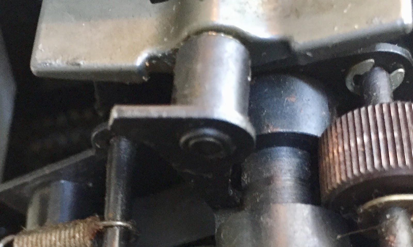
The other issue with the printer was that the carriage was moving steadily towards the right margin - continuous spacing. Working on this took the majority of the day. The spacing mechanism involves a clutch about dead in the middle of the shaft. Its trigger and stop levers were frozen in place.

Even with lots of clock oil and work, I didn't get the levers moving any better. I might have to do a more major disassembly of the printer to free this up. In preparation for that, I removed the carrier from the rest of the printer. The carrier has the typebars that swing up to print the characters, plus the ribbon mechanisms.

We put the carrier into a bath of Simple Green and will leave it for two days, after which I will dry it and oil it to make sure the typebars move smoothly and rapidly. I can't just dunk the rest of the printer in the bath because there are some parts such as the selector magnet that shouldn't be put in the cleaner. If I disassemble more, those pieces can be cleaned by the same method.

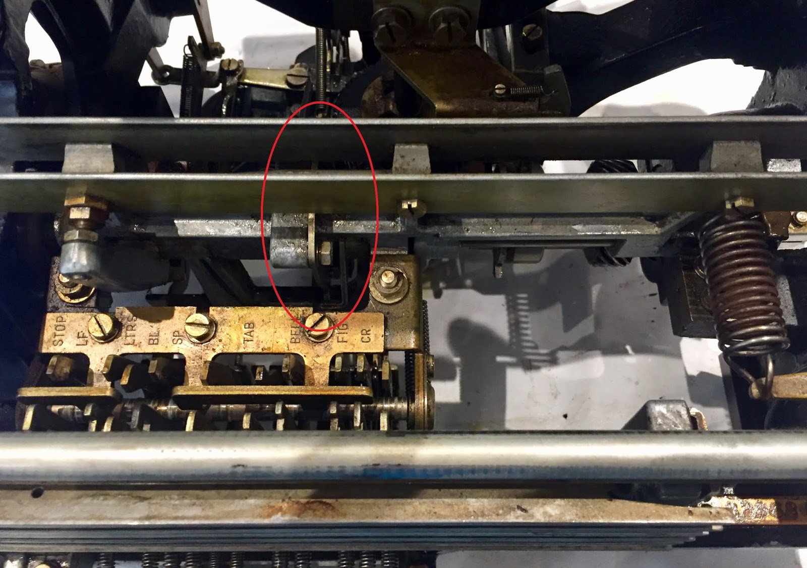
Quite a bit of the printer is also hampered by dried lubricants. There is a function mechanism that rotates forward to operate any function lever whose slots exactly match the settings of the five code bars. For example, if the code bars select a carrier return, then the function lever that matches the code drops forward and when the function mechanism rocks, it drives the levers to trigger a carrier return.

The function mechanism was not moving to its full range and was very hard to move. I worked it for a while and improved it quite a bit but more is needed. The function mechanism has to release the code bars in order for the selector mechanism to set them up with the incoming character code. Right now that doesn't work.

One of the function levers is the 'space' character, which should trigger the space clutch to take one rotation and move the carrier over by one column. Since it is not reliably triggering or stopping, it either moves steadily rightward or doesn't move at all.

The other thing that should happen is a print cycle, if it is a printable character set up on the code bars. That didn't happen at all, probably due to the stiffness of the function mechanism.

Basically, all the parts are on the printer and not rusted, but it will take quite a bit of work to get everything moving properly. The odds are high that I will have to disassemble it further to get it clean enough.

MODIFYING SBC 6120 (PDP8 CLONE) TO RUN AT 110 BAUD

I built the Single Board Computer 6120, which is a PDP-8 replica. Intersil designed a microprocessor that was a copy of the PDP-8, used for a while by DEC to build products such as the DECMATE, the 6120. This board is built around the 6120 processor, supporting a front panel that mirrors the panel of a PDP8 although it is scaled down in size a bit.

The board has jumpers to set the speed of the serial port, allowing four options with the slowest at 300baud. The ASR 33 needs to run at 110 baud. I looked at what might be possible to interface this computer to the teletype.

I had discovered that the serial port is driven by a TTL oscillator chip to drive the baud generator, separate from the clock that drives the rest of the circuitry. Therefore, if I can slow down the baud generator by the ratio of 110/300, it would make the slow jumper actually operate at 110 baud.

Main oscillator at 5MHz and serial port oscillator at 4.9152MHz
The original oscillator was 4.9152MHz and I was able to find a compatible TTL oscillator that runs at 1.8432MHz thus the effective baud rate is 111.7, close enough to work perfectly.

New oscillator chip at 1.8432MHz makes 300 baud = 111.7 baud


Tuesday, July 10, 2018

ASR 33 input received perfectly, can't get PC to RS232 link to output anything

ASR 33 TELETYPE RESTORATION

The model 33 is performing nearly perfectly already. The sticking that occurs where you a keypress isn't recognized has dropped to perhaps one in fifty presses and it recovers faster. I expect that with just an hour or so of use the stickiness will totally disappear.

I built the MAX 3232 board onto a bit of PCB breadboard, along with a header that will fit onto the Altairduino and a zener diode regulator to drop the 5V from that socket down to the 3.3V needed by the board. The SBC6120 runs on 5V, thus I build a quick socket for that system to plug in my MAX3232 based board.

Alas, the MAX board was so small and fragile, with tiny flat pads to solder on wires, that it broke before I was able to use it. I did have a different and slightly larger board in a different project box, which I rescued and hooked up.

Armed with my RS 3232 board which converts 3.3V RS 232 signals to true RS 232 (approx +/- 12V), I tied together a chain of modules to link my PC to the ASR 33.
  • On the PC, I ran the PUTTY terminal program through a USB to serial unit based on the Si2102 chip, modified to run at 110 baud when the PC selects 1200 baud rate. 
  • The si2102 provides RX, TX (and other RS232 signals such as DTR) which I wire to my MAX 3232 board. 
  • The other side of the MAX board produces RX and TX as true RS232 voltage levels. 
  • Those +/- 12V signals are connected to the Telebyte 65 converter, which turns the voltage levels into the presence or absence of a 20ma current on its output loop. 
  • The current loop is connected to the teletype where it drives the printer and paper tape punch
  • The Telebyte also provides a 20 ma current loop to the teletype for the transmission side, the keyboard, answer back drum and paper tape reader
  • This second 'send' current loop comes back as RS232 data, converted to TTL levels and sent back to the terminal program over the USB lnk
First, I tested out the Telebyte unit. I hooked up an ammeter and verified that it is supplying 20ma current on the two loops (receive and send) that will be hooked to the teletype. Next, I checked across the RX, TX and ground pins to see that pin 3 is output when in DTE mode and pin 2 is output for DCE mode.

I wanted to get the polarities correct for all three units - ensuring that the USB module delivers data from the PC outward on the RX pin, that this is the input to the MAX3232 and the RX pin output of the MAX is delivering that data into pin 2 of the Telebyte where it will modulate the receive current loop.

It took a few tries to get the correct configuration of the Telebyte 65, before I turn on the ASR 33 in Line mode, have it humming quietly in idle mode. It now sits in idle mode when switched on to Line, with the keyboard sending data without it appearing on the printer so I have achieved full duplex operation as intended.

Next up is to get all the RS232 wires hooked in their proper orientation. For example, the CP2102 USB to RS232 module will appear to receive data on the TX pin (since when I brushed it to ground the PUTTY screen showed invalid characters arriving. ON the other hand, the MAX3232 board has TX shown as inbound to the RS232 side, thus I have to cross RX and TX between these modules.

I then see that the RX pin, pin 2, of the RS232 side coming out of the Telebyte module is active (-13V for the MARK or idle input condition). Therefore , this pin is going to be the input into the RS232 voltage side of the MAX board, the RX pin.

This means that data from the teletype keyboard flows out of the current loop, through the Telebyte and out of pin 2(RX). That pin should be hooked to pin 2 (RX) of the MAX3232 side for RS232 voltages. It will deliver the data on the RX pin on the TTL/3.3V side. That data from the RX pin of the MAX is crossed over to enter through the TX pin of the CP2102 USB module and is transferred up to the PC.

After some wiring of the RS232 cable I have, to link the pins on the Telebyte to the pins on the MAX3232, I could run a test trying to send and receive characters between PUTTY on the PC and the keyboard/printer. My initial setup is a maze of jumpers, alligator clips and other temporary scaffolding but eventually it will be proper connectors.

I can see the keyboard input modulating the "TTL" side of the MAX3232, and the keystrokes are immediately rendered correctly on screen by PUTTY. However, nothing I type on the PC is received at the teletype. The problem is somewhere in the USB module, device drivers, Windows or PUTTY. I don't see the little LED on the USB module flash when I try to transmit data back to the teletype, so it isn't even trying.

I made a try at hooking up the Altairduino, which I had worked on earlier to remove the bluetooth module and use it as a native serial port. Unfortunately, it is not working properly now. I can't get it to reset properly or configure or speak over the USB link. Having reached the end of the day working outside in the heat, I packed away everything and will try again tomorrow. 

I am in contact with a supplier of teletype parts, RTTY Electronics, and will be able to buy every part that is missing on my system except for the spring holder for the paper tape punch. Marc will machine a replacement for me.

Monday, July 9, 2018

Prepped the Altairduino to drive the ASR 33 teletype for VCF West exhibit

ALTAIRDUINO HOOKUP AT 110 BAUD

I removed the bluetooth module from the Altairduino motherboard and replaced it with a header strip. This will allow me to plug in the bluetooth module, with its male header strip, or the MAX 3232 board with its male header, depending on whether I want my serial line to operate direct or wirelessly.

I foresee a third option, where I can have a TTL level serial adapter hooked up to the Altairduino - in this case there is no need to convert to true RS 232 voltages. It won't be used with the ASR 33 hookup but might be helpful in other situations.

I built a male header on a small PCB section that also mounted my MAX 3232 module, allowing it to plug into the rear of the Altairduino or to a different female header I will use with the SBC 6120. The small board will deliver +/- 12V receive and transmit signals that have to be connected to my Telebyte 65.

Next step was to permanently wire the small board I built to the Telebyte. The MAX3232 supports two in and two out connections, typically RX, TX, and then CTS/RTS or DTR or other control signals. I don't need any controls so I tied the spare inputs to 3.3V for the TTL in and ground for the RS232 in.

The header where I plug this board provides 5V, but the MAX3232 needs 3.3V supply even though it can handle 5V inputs on the TTL side. The Arduino Due that powers this machine runs on 3.3V thus I know I have access the the proper voltage somewhere, if I can only find it and route it appropriately.

This slightly spoils the symmetry of the socket which I intended to plug the bluetooth or the MAX232 boards as required, since the bluetooth model demands 5V supply. I hoped there might be a workaround, however. The header for these two devices is six pins across, but the active connections on the bluetooth module are only the center four. One end is used for 'state' and the other for 'enable'.

The 'state' pin senses the state of a LED, thus if I can't provide 3.3V through that pin. I looked up the module documentation to determine this. The 'enable' pin actually toggles the module between command and data modes, not something I want to mess with.

This tells me I have no safe pin on the header to deliver 3.3V. Instead, I will need to create a metod on the small RS3232 PCB to drop the 5V input on the pin down to 3.3V for my module. The bluetooth module spec is 50ma at 3.3V. Using a 3.3V zener diode and a 33 ohm resistor I will increase the current draw but the Altairduino is powered by a wallwart supply with plenty of capacity. The diode is on order and should arrive later this week.

Saturday, July 7, 2018

Finishing up ASR 33, preparing for VCF West exhibition August 4-5

ASR 33 TELETYPE RESTORATION

I worked on my ASR 33 a bit today. It still sporadically 'sticks', which I suspect is some old lubrication inside the keyboard module that is holding the universal lever from restoring fully. Until it does, pushing a key does not trip the clutch to run a distributor cycle and serialize the character value.

I watched the H lever which connects the keyboard module to the printer unit and it was properly resetting. No effect from prodding of the H lever, if the keys were unresponsive they remained so during prodding.

It works almost well enough. I can usually get 3-5 characters before a freeze, which releases within about 30 seconds in most cases allowing further keypresses. I ran through every character on the keyboard, in both regular and shifted mode, plus some control characters. They all printed cleanly and worked perfectly.

Typed output
I loaded my paper tape punch with some blank stock and used a forcep to hold the tension spring up to put pressure on the tape. I was able to successfully punch a sequence of characters onto the tape. That was ripped off and placed onto my paper tape reader mechanism. When I flipped the lever to START it ran through the tape and it all printed on the paper exactly as it was first entered.

Some punched tape - manually holding tension spring thus over and under tensioned
At this point, I have the broken part in the punch to work on, the sticky operation which I hope will work itself out over time, and still must verify that it works well with 20ma current loops while in LINE mode. All minor tasks with the teletype essentially fully restored already.

PREPARING FOR VINTAGE COMPUTER FESTIVAL WEST EXHIBITION

I agreed to bring the teletypes and exhibit at VCF West in early August here at the Computer History Museum. My idea is to connect the ASR 33 to either or both of my vintage computer clones - the SBC 6120 and the Altairduino. The SBC 6120 is a PDP8 clone which leverages the Harris 6120 microprocessor which is a PDP 8 implementation. The Altairduino uses an Arduino Due to clone an Altair 8800 system.
PDP8 clone using Harris 6120 processor chip
The problem is the teletype, which requires 110 baud serial port speed. Neither of the clones run that slow. The SBC 6120 can be configured for 300 at its slowest. Similarly, the Arduino Due lowest serial opening speed is 300. I had to investigate ways to modify these to operate at the proper speed, using the software and hardware of these two clones.

The SBC 6120 uses a small four pin TTL chip to produce 4.9152MHz which is divided down to run the serial port. The hardware has four jumpers to set divisors for 38,400, 9600, 1200 or 300 baud. I found a similar oscillator chip that runs at 1.8432 MHz. That reduces the baud rate with the slowest jumper to 111.7 baud. Typically you can be off by +/- 5% in speed and still work well, so my +1.5% is going to work well.

one of these silver cans is the 4.9152MHz baud rate generator oscillator
The Altairduino serial port libraries do not support 110 baud but reading the spec sheet of the Atmel ARM processor chip shows that serial ports 2, 3 and 4 of the chip can be set as slow as 80 baud and as fast as 5,250,000 baud. It will take some code hacking to reconfigure the serial port, which hopefully I can do with minimum impact on the clone software.

I went to the github repository for the Altairduino and starting investigating the configuration code. I saw that it had entries for 110 baud, which implies that this is indeed able to drive the ASR 33 without modifications. The only question is whether the version I built has this functionality or if I have to update to get it.

Then there is the pesky issue that I built my Altairduino with a bluetooth module on the serial port. I don't believe the bluetooth serial board can handle 110 baud, but I can detach it and run straight RS232 out of it.

I did an experiment. Setting the USB Programming port as my primary console, I configured the serial port (bluetooth) to 110 baud 8N2 and attempted to connect to it  via PUTTY from my PC. I don't know whether the fault was in PUTTY, my bluetooth module in my PC or the bluetooth module in the Altairduino.

However, I have every reason to believe that I can remove the bluetooth module and bring out the RS 232 RX and TX lines. The only issue is that these will be 3.3V logic levels.

To connect these machines to the ASR 33, I need to convert voltages to the +/- 12V RS232 levels and then convert again to 20ma current loop. I have a Telebyte 65 converter box for the latter requirement and only need to add in a MAX 3232 based board. The 3232 chip handles 3.3V on the "TTL" side.

CP2102 USB to serial in front, Telebyte 65 RS232 to current loop in back
To test with a PC, I will use my CP2102 based USB to Serial chip, which can be configure to run at 110 baud, hooking that to the MAX 3232, the Telebyte 65 and the Teletype ASR 33. The only board I don't have on hand is the MAX 3232 which I just ordered. It should be here by the end of the weekend.

The other part of the exhibit will be a model 15 teletype, printing out weather reports and news stories much as they did in newsrooms druing the middle of last century. I already have the software and interface hardware for the model 15 which will drive this demo. BaudotRSS provides the softwre feed at 110 baud and John Nagle's TTYloopdriver module drives the teletype. All I need to do is make sure I have a restored model 15 working properly. 

ASR 33 together and mostly working properly; progress on model 15 teletype keyboards

ASR 33 TELETYPE RESTORATION

I brought the printer unit to Marc's basement and put the entire unit together. Initially I found that the local loop from keyboard to printer wasn't working, but that ended up as a configuration error on the rear panel of the Call Control Unit.

When switched to Line mode, the printer chatters (as it should) because the line is in a SPACE condition which is interpreted as a continuous stream of null characters. Switched to Local mode and it quiets right down, waiting for a keystroke, Answer Back operation or paper tape reader input.

When I hit the Here Is key, it triggers the Answer Back drum, firing off the characters on the drum. Since it is a new drum with nothing set up, it produces a series of null characters, making the printer chatter while it runs.

When I push down on the tape testing pin on the tape reader and set it to Start mode, it interprets the tape as an invalid character, treated as a null causing chatter. Once I produce a tape or find some existing paper tape code to read, I can verify the operation of the reader.

I began pushing keys which printed the selected character on the paper. CR, LF and BELL worked fine as well. The problem I faced was sporadic failure to respond, a period when no key would trigger the machine to serialize the key value. After a bit of time, the keyboard again responded.

I did find that slight tapes on the right front side of the teletype cover would often prod the keyboard to respond again. This may be an issue with the alignment of the keyboard module relative to the printer unit, something I can play with tomorrow.

I can't test the paper tape punch yet because of the broken arm that would be used to tension the spring which puts pressure on the incoming tape. No tension means the tape won't be moved forward as it punches. This is a high priority to repair, first with a temporary workaround and later with a correct replacement part. 

MODEL 15 TELETYPE RESTORATIONS

Marc's model 19 has a keyboard with a built in tape perforator and character counter. The operator could punch tape from keystrokes, without seeing it echoed back on the printer. The column counter will show how far across the line one is, allowing judicious CR and LF to be added once the line is too long.

After a careful cleanup and oiling, Marc set to adjusting the punch. Several adjustments had to be tweaked to cause the perforator to punch correct patterns and advance the tape smoothly. These machines used oiled paper; the oil helps keep the punches lubricated.

To check out the operation one needs the keyboard mechanism to be rotated by a motor at a reasonable speed to produce characters at 45.5 baud. The base unit of the teletype has a motor built in and the keyboard slides into the base, but the gears don't mesh. The printer unit must be placed on the base, as the main axle of the printer includes gears to engage both the motor and the keyboard.

We didn't have a printer mechanism that is ready to run under power, as they are all nearly frozen or maladjusted. Marc put together a temporary stand and coupling to spin the keyboard shaft with a small motor he could power with a variable voltage power supply. This allowed the keyboard mechanism to rotate at the proper speed, waiting keystrokes to fire the clutch and serialize each character.

The perforator is attached to the keyboard and the same code bars that set up the five bits for serializing and transmitting will also set up the interposers on the punch unit. If a code bar is in the MARK condition, the interposer is in between the punch rod and the armature of a solenoid. Those with SPACE conditions have no interposer. When the armature moves upward, it pushes the punch rod up into the die for every position where a hole is needed, thanks to the interposer.

The solenoid that rams the punch rods upwards requires about half an amp of current - it must be powered with a relatively high DC voltage. Marc used a 100V DC power supply with current limiting to drive the solenoid. The solenoid is triggered by a microswitch on the rotating keyboard encoder shaft.

To start the tape, one has to punch the small sprocket holes that sit between columns 2 and 3 - this is used to pull tape forward on both the punch and on readers. The bottom right key, with nothing printed on it, is the BLANK key and it punches a character with all five bits set to SPACE.

The BLANK produces just the sprocket hole on the tape and a series of these produces the leader before you begin punching the actual output message. The opposite character to BLANK is the LTRS (letters) key, whose code is five bits of MARK. This punches every hole in the tape.

After the adjustment to punch all holes with LTRS and no indentations at all for the 5 bits with BLANK, we tried some other characters to check the proper encoding. The ITA2 or USTTY encoding used with these 5 bit machines has two useful characters - R and Y - whose patterns are 10101 and 01010. We got those correctly, as well as general typing rendered properly.

Th column counter is not working yet. We didn't have time to debug it. Another microswitch on the keyboard encoder axle should advance the counter, while it should reset to zero when a CR is encoded (01000). We haven't looked at the mechanism yet to learn how it should work, nor to diagnose its current fault.

Our oscilloscope was hooked up to monitor the serialized output from the keyboard encoder. We saw that our bit timing is very close to the nominal 22 ms produced by 45.5 baud operation. Further, we saw properly encoded characters for everything we tried. BLANK has five SPACE bits, LTRS had five MARK bits, while R and Y alternated the patterns of 10101 and 01010.

Marc and I visited the spray shop that is sandblasting all the external metal parts of the model 19 and then powder coating them. Powder Coating bakes on a color finish in an oven after the color powder is sprayed and sticks electrostatically to the metal part. A very high voltage charge is applied to the spray gun and the metal parts are grounded.

The parts looked superb after the sand blasting - it removed the dings and holes which were essentially all in the layers of paint that were accreted during the machine's years of Navy service. Marc chose a black with a fine texture. We are looking forward to completion of the power coating on the 39 separate metal items that are part of this model 19. 

Thursday, July 5, 2018

Finished checkout of ASR 33 printer unit and punch

ASR 33 PRINTER UNIT RESTORATION

Before I could install the errant spring, I had to find it. I believed it was somewhere inside the printer mechanism, which led to a very slow and careful examination from all angles. This went on for quite a while, turning the mechanism on the two stable ends and trying a third less stable orientation in the hope of dislodging the spring.

Finally, when I had all but given up hope, at 9:30 at night, the spring appeared underneath. I put it in the parts bowl for now, planning the next attempt to attach it for the next morning. I picked up a great idea from Jack Rubin - tie a thin thread onto the spring and connect the other end to a part of the machinery. This will allow me to locate it quickly if it again 'springs' away.

Loose spring with thread tied to it and to printer mechanism
Using the safety thread to protect me from any further hunts for a needle in the haystack, I maneuvered the spring with the gripping tool and two springhooks. I wedged the gripping tool and its end of the spring over the top bar near where the spring should attach.

I then pulled the bottom of the spring down, transferred it to a springhook with a 90 degree end, perilous since the spring can easily slide off the hook end unlike the normal curved ones. However, this right angle springhook allowed me to pop the spring loop over the bottom mechanism and ever so gingerly remove the springhook itself. Success!

Spring in place on the bottom of the mechanism
I now had the spring attached at the bottom but needed to transfer its top loop over the projection on the top bar. With just the gripping tool, I got the spring on the bar. Removing the gripping tool requires some twisting of the spring loop which can detach it. It took about five minutes moving a glacial speed but I did remove the gripping tool with the spring still attached.

Spring attached to top bar and thread still tied to middle of spring
Using scissors with great care, I managed to cut the thread around the midst of the spring and pull the thread away. Removing the other end of the thread, fastened to the top of the printer mechanism, was child's play. The top of my spring is hooked over the top bar, not looped around the projection intended for it. This positions it slightly to the right of its ideal spot but I think this is good enough.

With the spring restored to bit 4, I can use my power supply and timing chart to set up the characters or functions I want to test. A rotation of 12 vanes is one bit duration; about 140 is a complete spin of the selector cycle to handle 11 bits and trip the code bar clutch.

With this in mind, I was able to encode a carrier return character and watch the function section attempt to release the carrier to slam to the left. Indeed, the carriage sprang to the left as the encoded character was executed. There is a release lever that should latch the carrier to the spacing mechanism once it hits the left side, but it is not releasing.

After studying the documentation for the involved mechanisms, I discovered that this is normal behavior. The carrier return function disengages the spacing mechanism as the carrier slams back to the left. It remains disengaged so that the carrier can be freely moved to the right and snaps back.

When a subsequent spacing operation occurs, either a space character or any printing character, the spacing mechanism moves one to the right and reengages to hold the carrier at column 2. I encoded the character W, watched it print, the carrier space over to column 2 and stay there.

Following that, I coded for a line feed to test that function. It did take a few tries before I produced exactly the bit pattern I wanted. The platen rolled upward one line, exactly as expected. I even coded up the 'bell' function code and heard it ring.

With such good results, I decided to wire up the printer unit to 110V for the motor and to my 300ma low voltage DC supply for the selector magnet. The expected behavior is to have the unit settle into the idle condition. What happened was exactly that.

Hooking up 120VAC for motor and DC to operate selector magnet
Dropping out the DC supply should give me chattering of blanks without printing or advancing across the page. That also occurred exactly as expected.

Twisting the keyboard activation lever should fire off one round of encoding a blank and then taking a non-print cycle, with the machine in LOCAL mode. Instead, the distributor fired but since I don't have the cabling in place to implement LOCAL or loopback mode, the printer unit continued to sit in idle. Still, I verified that the distributor clutch was operating properly.

In addition to triggering a distributor cycle to serialize the keyboard input when I rotated the keyboard trip lever, I pushed on the Answer Back lever and saw the drum rotate through its positions and the distributor serializing the programmed characters.

I switched on the paper tape punch and dropped DC power, which would give me blanks and should attempt to punch them. Indeed, the punch unit was attempting to punch when switched on, although with no paper tape inserted and with nothing but blank characters, this isn't a full verification.

I still have a problem with the tape punch unit, because of the broken arm used to adjust the tape roller pressure. A spring is hooked to one of a number of notches on a projecting arm, which sadly was broken off and lurking inside my punch unit.

I have emailed a service that used to provide Teletype parts from an enormous inventory, but no word back yet. Since I emailed at the start of the holiday week, it is possible that the owner is away and will respond next week.

Even if the parts service is no longer in operation, I should be able to fabricate a suitable replacement and fully repair the punch. For the immediate future, I am happy using the printer without tape punching.