Saturday, February 28, 2015

IBM 1132 Printer reassembled and testing underway

1132 PRINTER RESTORATION

I can't get the clutch latch lever assembly out for a proper cleaning, because it is situated where it would require almost total dis-assembly of the printing engine to reach the attaching screws. As well, all the places I need to get new oil inside are all above where I can access them - hard to get oil to seep upwards.

This makes it a very slow process - the clutch latch lever slides into two 'comb' structures as well as rotating around a pivot rod. Sludge in all three places contribute to sticky levers. The have a spring inside that should push the lever immediately outward, but many either stick in the wrong position or creep out very slowly.

After several hours of persuasion and lots of washing out and drying with an air can, I had all 120 columns moving adequately well. Time to figure out how to get oil into the parts I just cleaned. Once I put oil on the parts, I can begin assembling all the removed bits of the printer.

I decided to pick up a small oil sprayer, originally designed for gardening and similar tasks, as this should let me spray enough oil in to do the job. I picked it up at Lowes and while it spurted more than sprayed oil, it was enough to get the key points covered with oil.

Reassembly was a slow and careful process. The comb bar that partly covers the clutch latch levers was first to go into place. As I tried to fit the restoring levers in place, I found it impossible to get the locating pins to slide in, even with the bolts loosely threaded. I took a break, checked my manuals, and discovered I was trying to install it upside down!

With the restore latch assembly oriented properly, I found its installation to be quite a bit easier (doh). Note that this is still not easy - it took about 40 minutes of painful wrestling to get to the point where the first pin could slide into the latch bar, even with the bolts in place. The second pin took another hour, because there were plates and other objects in the way that made it almost impossible to use a hammer and rod to drive it in. Glancing blows and pressure did very little. Quite annoying.

Once the restore levers were in place, the cam detente lever assembly was next to install. That was already held in place by one of the two sets of bolts, thus only needed to be rotated into position, pins pushed in and then the final pair of bolts installed.

The idler gear on the gear train had been loosened and slid partway off its shaft just to permit the bolts and pin for the restore lever assembly to have been loosened. I had to push the gear back in place - these are bakelite gears on a steel hub, not all steel, interestingly. The circlip put back on the gear shaft, it was ready to rotate.

The magnet assembly has the 120 solenoids plus the two levers per column that extend the action of the solenoid to push the clutch latch lever off the cam disc clutch dog. I slide this assembly into place and bolted it down. At this point, the printing mechanism itself was completely installed, but a few tasks still remained.

Print mechanism back together, ready to start testing.
After a check of all the bolts and attachments, to verify it was back together completely, I was ready for a test of the printer. First up was a power on inspection - followed by turning on the motor to see that the mechanical bits weren't crashing together or chewing themselves up. No damage but it was printing all 120 columns continually - kac-hing ka-ching ka-ching ad infinitum.

I am investigating possible causes and figuring out what to test to confirm the diagnosis. Not sure I will be able to move forward today, with this small setback. On the other hand, all columns do print which means I have free motion of the print wheel hangers.

I suspect that it is the way I assembled the magnet assembly (solenoids) - as these levers should hold the clutch latch in, keeping the dog from engaging to spin any disc. I will try removing and more carefully re-installing the assembly, which hopefully will resolve the problem.

Once I have this problem identified and fixed, it will be time to hand toggle a program to print some characters. Probably tomorrow since it is after 9PM already.

Most printers have a control unit with logic to handle details such as matching a desired character to the current type element that is flying past on a wheel, drum or chain, triggering the hammer at the proper time, and therefore just accepts a print line from the program and interrupts to signal completion.

Not so with the bargain basement 1132 printer. Much of the work of printing a line, that would be built into the printer itself or a control unit or as a printer driver inside a different system, was left to the software in order to skip the cost of additional SLT cards.

The printer has a set of 120 wheels, one per column, that rotate at a bit over 100 RPM. There are 48 positions around each wheel, thus the printer supports 26 alphabetic characters, 10 numeric and just 12 other characters to handle period, comma, question mark, exclamation, pound sign, dollar sign etc.

The end of the print wheel shaft has a metal disk with several concentric rows of circles that are read by photocell detectors. The disk has holes punched in the concentric circles to encode which character of the 48 is about to rotate into proper position for printing.

The programmer may make up a print line of characters, but that is not sent to the printer. Instead, when the line of print is read to be printed, the programmer issues a command to the printer, Start Print, which begins interrupting the 1130 each time a new print character of the 48 around a wheel comes into position on the encoding disk.

In addition to sending the interrupt for each print wheel position, the 1132 clears out a bit in a special fixed area of core memory. This bit must be set on by the programmer before the printer mechanism has rotated to the point where it has to fire hammers to print the current character. If the bit is not on, the printer detects a 'sync check' which means that the software wasn't fast enough to set up which columns to fire.

The program handles the interrupt by issuing another command, Read Emitter, which returns one word which is the value encoded on the disk. Now that the character is known, the software looks over its print line and finds which columns, if any, have that character to print. The fixed area in core memory is set with a 0 if the column is not to print, or a 1 when the cam disc should rotate to slam the print wheel into the ribbon and paper. Columns 1 through 16 are handled by the first word of the fixed area, location 0x0120, columns 17 to 32 are in 0x0121 and the final word in 0x0127 has 8 bits for columns 112 to 120 plus a final bit that is set to 'prove' to the printer that the line is ready to print.

The interrupt for a character precedes the time when the wheel is in the proper position to print, giving the software time to be interrupted, read the emitter value, look through the columns of the print line and set up the bits in words 0x0120 to 0x0127.

The printer executes cycle steal operations to fetch the eight words of memory starting at 0x0120, preparing to unlatch the clutch dog on any column that should print. When the mechanism is ready and the character is ready, the solenoids fire and the cam discs spin around for the chosen columns.

The program remains waiting for further interrupts, as various characters come into position around the print wheels, each time firing the columns that should print the current character. This may progress 48 times if the line has every possible character in it, but the print line could have all its characters completed before that point arrives. If so, the program issues the commend Stop Print which blocks any further interrupts or cycle steals.

The program then has to delay a certain amount of time to let the mechanical process of spacing down one line to complete. If the software wants to skip ahead to a given position on the carriage control tape (one of 10 channels, 1 to 9 plus 12, will have a hole punched on the line where the printer should stop).

The printer then interrupts the 1130 for every line where one or more of the channels is punched, allowing the program to decide if this is a match to the intended stopping position. If the user wants to stop, a suitable command is issued to the printer otherwise it keeps moving down the page.

On most other printers, the software would issue one 'print' command, point to any location in memory that begins a 120 character line, then wait until the interrupt came in with status - hopefully that the line printed correctly. Quite a bit more programmer friendly than was the 1132.

My hand coded test to be toggled in, is intended to print my name plus a space repeated across the entire line. The program looked at the code from the Read Emitter operation, firing columns only when we saw a 'c', 'a', 'r', or 'l'. Pretty simple but it does verify much of the printer operation.

SAC INTERFACE FOR ADDING PERIPHERALS TO THE 1130

I removed more signal pairs and labeled them - all of old board two is now done. Just 29 more signal pairs and I will be done. Having freed up enough room to work, I could remove the Digilent FMC Carrier S6 board and the Xilinx FMC Debug card, making room to install my new ZTEX Spartan 6 fpga board when it arrives.

The fpga board was transferred from Deutsche Post to an air freight carrier in Frankfurt two days ago, which presumably means it is in the US and clearing customs now. I hope to get a further update once it is transferred to the US postal service. My new PCBs for the interface circuitry are in process - a 72 hour turnaround was purchased - after which they will be forwarded to DHL Express for a 3-7 day transit to my home. With luck, I will receive before the March 7th but certainly before the following week is out.

Friday, February 27, 2015

Beginning cleaning of final 1132 printer levers, nearly done with rehabilitation

1132 PRINTER RESTORATION

I opened and worked on the clutch detent lever assembly some more and am now satisfied it is working properly. I inspected and tested all 120 clutch dogs (the lever on the side of each print cam disc that will rotate down into a slot on the axle when it has been released, so that the cam will spin around once to print a character). It is time to re-install the guide bar and clutch detent bars on the machine.

What is in awful condition is the set of clutch latch levers that sit at the bottom rear of the clutch cam disc group. These should pivot inward and hold the clutch dog out of its slot untl the clutch latch is released by a push from the solenoid actuated rod. The restoring lever pushes the clutch latch back into position so it can hold the clutch dog and thus stop the disc from making more than one circle of the shaft on each actuation.

Clutch latch levers at bottom, pivoting into the clutch discs
I am going to try to flood the pivots with oil or otherwise clear them, hoping that they begin to move as the should. It would be best if I could lift them (the entire bar of clutch latches) out of the machine as I did with the other lever assemblies, but this requires a ton of additional disassembly first.

Specifically, I would have to disassemble the gear train, remove bearings and lift the cam clutch cylinder with all 120 cams out, then disconnect and lift out all 120 print wheels. Not only a lot of work, but it introduces the need to do timing and adjustments I would rather than disturb unless I absolutely must.
Gear train that would have to be disassembled, along with print wheels, to lift out clutch latch assembly
The print wheel hangers have a pivot that is right on the top, directly accessible for lubrication, which is perfect for my purposes. I don't think I need to remove the print wheel assembly, as a result. It means that the only issue standing between me and a working printer is the set of clutch latch levers.

Pivot bar for clutch levers visible on left, sticky levers pass through guide bar on right
I spent a bit of the afternoon out working on the clutch latch levers. To have better access, I had to remove a bar that provides grooved supports for the spinning cam clutch discs - this had two allen head bolts holding it on. The left bolt was so frozen in place that I was gradually destroying the allen shape in the head, no gripping tools could turn it from the outside, and it was clear I had to do something extraordinary to remove it.

Troublesome allen bolt, before forced removal
The solution was a chisel and hammer, cutting a slight groove on one side of the bolt head, then striking it at a near tangent angle to force it to rotate. I was able to get it turning and remove it the rest of the way with a normal allen wrench. The bar then had to be persuaded to come loose - its locating pins kept it snugged up even boltless.

With the key points on the clutch latch levers being above my access point, the oil will have to be forced upwards against gravity in order to lubricate it. Washing the surfaces with oil is not an option. I had to use a residue free spray cleaner to free up the gunk, after which I will oil the mechanism as best I can.

Even with the spray, it takes time to work each lever until it moves freely enough to work properly. They should all pop out as they have springs to pull them out to the rest or triggered position. When a solenoid activates, its long lever will slip this latch lever off the clutch disc dog, the spring will pop this clutch lever out, and as a result the clutch dog will be pulled into a slot on the clutch disk shaft, spinning it around.

Late in the rotation of a disc, a wider part of the disc circumference will push on the restoring lever, which in turn pushes the clutch latch back up into contact with the clutch dog. That resets the dog out of contact with the spinning shaft, then the detente levers hold the clutch disc in the rest position until it is triggered for a later print operation.

My print wheel hangers are rotating well, so everything is ready for printing once I get these clutch latch levers working smoothly. It took about 20 minutes to get a group of 15 columns moving freely, so about two or two and a half hours more to work through all 120 columns.

I didn't finish this tonight, so more to do tomorrow until I have all 120 of these clutch latch levers working well. A bit tedious but straightforward.

Right-hand group of clutch latch levers freed up and moving well
Perhaps 30 minutes additional will be needed for final oiling of the mechanism and then I can begin reassembly. I feel good about the chances I will have a properly working printer at the end of this effort.


READ TAPE OF 1130/1800 SOURCE CODE

I met with Lyle Bickley, who will help by reading the tape and storing any content in a transferable file in simh (widely used machine simulator) format suitable for use with the IBM 1130 simulator. I can then send it to the owner.

SAC INTERFACE FOR ADDING PERIPHERALS TO THE 1130

My components came today for the new SAC interface cards - 50 of each resistor in 0805 size surface mount, 100 of the 33uf tantalum capacitors in surface mount 1206 size, 150 BV52 transistors in surface mount SOT-23 size, and 50 1N4148 signal diodes as discrete (wire-through) parts.

I also spent some time verifying and tagging all the signal wire twisted pairs that will go on the new cards, coming from the large cable connector out to the 1130. I completed the first of the old cards, 12 input and 12 output signals, plus 12 input signals from the second old card. There is a third old card plus five extra circuits on an otherwise bare fourth old card; these signal wires should all be labeled correctly, ready for assembly to my new cards.

Thursday, February 26, 2015

More 1132 printer cleaning, rehabilitation and oiling

1132 PRINTER RESTORATION

Spent a couple of hours working on the printer - freeing up restore latches and ensuring the cam clutch discs rotate. The restore latch bar has one of its attachment screws directly behind the edge of an intermediate drive gear, which prohibits removing the restore latch bar unless I disassemble the drive and quite a bit of the rest of the printer. Going to work on the latches without further removal.

I oiled the pivot points of the print wheel hangers, but it is hard to move them except by rotating the cam clutches. These won't relatch into the idle position due to stiffness in clutch latch levers, which are devilishly hard to reach or work on with the cam clutch shaft in place.

Oiling and moving the restore latches, but a few of them don't pop back out as they should. It doesn't feel like sludge holding them, instead I don't feel the spring tension that ought to pop them back up. It might be dirt keeping some springs compressed, or it might be a spring failure.

The access to the restore latch springs is placed on the side and angled a bit downward, meaning that the latch bar MUST be removed to safely open the access and clean the springs. I am sorting out how to remove the intermediate gear, before removing the restore latch bar.

It worked out well enough to just remove the circlip and the bolt, slide the intermediate gear out partway, which gave me room to pull the teeth of the last bolt free from the bar without the bolt having to come all the way out. I put that assembly aside and looked at the state of the cam clutches and clutch latch levers. The latch levers seem very sticky, obvious from the uneven state they are in right now.

I will do my best to clean these up in-situ, because the removal requires removing the cam clutch shaft, cam clutches, and the print wheel assembly! Basically a complete tear-down, which I don't want to do. I think I can work oil into these and make them perform adequately.

Clutch detente levers at top, restore levers at bottom, plus guide bar on right
I read over the history of the restoration of an 1132 at the National Museum of Computing in the UK - they didn't take the unit apart as I did but their experiences show that it had many of the same sticky levers. At first, some columns wouldn't print or would print repeatedly or slam in the wrong character. Over time as they kept printing on it, the issues sorted themselves out one by one - symptomatic of the sludgy grease warming and clearing out through usage.

I had to open the spring access plate of the restoring latch assembly, clean and oil the springs, then carefully re-install the plate. That was extremely difficult, with 120 tiny springs attempting to bend around the edge of the plate. I was able to ultimately get them all installed and tightened down, work in lubricant across the levers, and ended up with this assembly working perfectly.

My cam detent lever assembly from before still has some columns that don't pop all the way out. I suspect that if I open the spring access plate again, I can get these all working properly as well then lubricate all the pivot points.

Cam clutch discs, with clutch latch levers visible at bottom of disc
Next up, tomorrow, is an attempt to clean and rehabilitate the clutch levers and the print wheel hangers without the total disassembly of the printing mechanism. If I am successful, I can put it all back together and do some testing.

Clutch latch levers, obviously gunked up and sticky

Wednesday, February 25, 2015

Continued 1132 rehabilitation, SAC interface boards out to fab

360/40 FRONT PANEL AUCTION

A reader of this blog pointed out an auction on eBay of a 360 model 40 front panel in good condition, designated as only for sale for local pickup by some from the bay area.  Because these don't show up often, I reluctantly bid on it, which would have created another enormous project - building an fpga replica of the 360/40 processor that would power the panel. I had mixed feelings and thus am not upset that I was outbid. Back to the 10,000 tasks already in my queue.

1132 PRINTER RESTORATION

In order to free up, clean up and relube the rest of the print mechanism, I have some disassembly to do. I began removing screws to lift off the detent latch and restoring lever bars along with their attached levers. These can be rehabilitated once removed. It also gives me more access to the print cams, where I can evaluate the feasibility of cleaning and restoring the cam, attached dog and the associated detent link as it sits. if that seems unlikely, I will then remove the print cam assembly which actually involves removing the carriage and lots of the rest of the printing mechanism.

There are several sheet metal shapes in place blocking some access to the screws for the restoring lever screws and the print cam shaft. I have to remove or loosen these enough to tilt them away when I am accessing certain screws. I got partway through before the evening arrived and I went in for dinner.

Later, I removed the top bar which was the cam detent assembly, moved it to the workbench and began to work in lubricant. I discovered the levers moved well enough but for some columns, there was noticeably less spring tension returning the bar to its idle position. I opened the chamber and boiled all 120 springs, working them in and out of their channels.

Detent assembly, the spring loaded levers should all be at extended rest position

Pivot side of the detent assembly - unevenness very evident

Closeup of sticky levers
Little springs in their channels, pushing the detent levers outward
With the bar back on, I still have a few columns where the bar doesn't return to the same position as the rest. Nothing is obviously wrong with the springs, but I might need to find replacements for the few that are weak. Less than five of the 120 columns are failing to spring back as strongly as the rest.

The next bar to remove from the printing mechanism is a double decker bar that holds the restoring latches. I will pull that out and get all of those working freely too. Each of these bars has the tiny springs inside, thus I may find a few more springs that need replacement. I actually don't know if the spring issue is bad enough to cause printing problems, but I can make a determination with the bar back in place; if the cam doesn't lock into position on the weak columns, the spring needs immediate replacement, otherwise it might be a longer term restoration task.

Cam discs in top half, double decker bars hold restoring levers (bottom half of picture)

I have enough room now to inspect the cams - a few are sticky but there is enough access so that I can get oil to all of them such that they will all rotate freely. The print wheels hang from a pivot that is directly accessible, allowing me to get enough oil in that I can assure they move properly.

Print wheel pivot points, one character on print wheels visible just above pivots in picture
Cam clutch disks, dog latch rotating on side pushes into the fluted slots in shaft to spin cam

Two mechanisms are still hidden and might force me to do more dis-assembly. First is the cam clutch latch which sits on the other side of the cams from where I am servicing them, and below the axis point too, thus directly behind the cam from my vantagepoint looking in on the machinery. Second is the dog latch with spring that is on each rotating cam plate - it needs to swing in and out  if the cam clutch is to engage to print a column - but with them deep in between the parallel cams, any dogs that don't free easily may require dis-assembly of the entire print clutch/cam unit.

Clutch latches are directly under the cams - far side from this point. Dog latches are on sides of discs. 

This will take a few more days but so far I am satisfied with the progress I am making. It appears to be possible to get this assembled again and printing well, just by finishing this cleaning and lubrication work.

COMPUTER HISTORY MUSEUM 1401 RESTORATION

I meet a small group from the restoration team at midday and we went to work on various parts of the systems. One group had to disassemble and repair the punch on the German 1402 reader/punch as it frequently jams. We discovered some misalignment of parts and wear, which forced the team to tear down the unit quite a bit.

I did a quick replacement of two console panel bulbs that had burned out on the Connecticut 1401 system, then turned my attention to a problem the German machine has with its tape drives. The system writes a string of characters, for example 123456789 then backspaces and reads them back. The write completes with  no error but the read returns 1337777 with check bit errors.

It seems that when you begin a record, any time a bit is on, it will stay on for the remainder of the record even if it should be off for that character. Thus, the 1 bit is on for the first character '1', then the 2 bit turns on while we still have the 1 bit active, so the '2' comes out as '3' (both 2 and 1 bits on). The '4' character turns on the 4 bit, making the 4 2 and 1 bits on for a '7'. This stays true until we get to character '8', which turns on the 8 bit but we still have 4, 2 and 1 thus a special unprintable character is returned for '8' and '9'.

I figured out how to turn on Bob Feritich's virtual tape drive, a bit of hardware that sits on the tape cable chain and acts like a 729 tape drive. We used that to write and read the pattern, still seeing the problem which confirmed to us that the issue is not in the tape drives but inside the electronics in the 1401.  By the time I left, we were scoping various signals to determine what was happening. It seemed like the bits were coming in correctly from the tape drive but somehow corrupted after that point. I ran out of time and left, so unsure of what progress was made for the rest of the afternoon.

SAC INTERFACE FOR ADDING PERIPHERALS TO THE 1130

I looked over specifications of fast switching transistors and discovered one, the BVS52, that slashes the storage time impact on cutoff, allowing my original circuit design, sans bypass capacitor around the base resistor, to operate with less than 20ns delay from when the incoming 1130 signal drops until my transistor cuts off allowing the output signal to rise.

I placed an order with DigiKey for all the components for my new board and will, after a few tweaks of the design and verification of the Gerber code produced, send it off for fabrication. The oddity about my design is that I accomplished all the routing on the board using only top side copper traces, thus I wanted to convert the bottom side to a power plane rather than a signal surface.

For historical reasons, the files for the interior power planes of most boards are negative, meaning they describe the shapes that should be removed from the copper layer rather than a positive file like the top layer where each feature in the file represents copper to be left on the board. The fabrication site will invert the gerber file for power planes to positive. Since this is a step done by the processor, not inherent in the gerber file itself, there is the risk of an error with nonstandard use of the bottom layer

I want  my bottom layer to be a powerplane will have copper poured across the area with small cutouts around all the via holes. I have to be sure that the gerber file will produce the right result, giving me the broad copper area with some holes, rather than metal rings around vias and a wide open area. I will have to inspect the detailed content of each gerber file to ensure it is interpreted reasonably by the board fabricator. I downloaded the protocol specification for gerber files, which are ASCII format files that are human readable.

I figured out how to get close to what I want, but it is complex to get the files the way the fab wants them. For example, I use OSHPARK to check out my files - they want the internal power planes to be positives not negatives. Have to regenerate the gerbers once again. I am much closer than yesterday, however, and with another hour of work I should be able to order my boards.

Having verified everything and carefully documented it all, I sent it to GoJGo.com where I had an urgent turnaround of ten copies of the four layer 6.5 x 3" board, silkscreen, solder masks, and automated testing of the result, all for $162 (plus $35 for DHL Express international shipment). I should have the completed boards back in less than two weeks, ready to assemble and then install.

Component view, one board hosts12 receivers and 12 drivers
Top view of board, before it is covered by green solder mask
Bottom view of board, copper ground plane plus green solder mask

DATACENTER SHED CONSTRUCTION

I picked up the epoxied together joint handle and installed it over the two breakers that cover my 240V single phase 20A circuit feeding the IBM 1130 system.

Handle installed over pair of breakers for 240V circuit

Tuesday, February 24, 2015

Creating SAC Interface boards

SAC INTERFACE FOR ADDING PERIPHERALS TO THE 1130

I spent four more hours fighting with the design tool to clean up the board design, after which I went through validating every shape and connection before placing the order. Near the end, I discovered that the design software for the transistor had an SOT-23 physical layout setup but it has the lone top electrode as the emitter, something that zero real transistors in this package would do.

I therefore have to update the design file for the transistor shape, see what it does to my board design and fight through all the consequences of the pins shifting around. I was ready to order all the parts and the board manufacture, but now I need to revamp the layout and recheck everything.

After another hour, having adjusted the component shape then rotated and rerouted the traces ot all 36 transistors, plus relocation of ground vias , I had a set of file that appear good. I will check them with some gerber file viewers to ensure they are good, before submitting them. This process took a couple of hours including iterations to satisfy one of the PCB fab web sites that conveniently checks designs.

I discovered that I had forgotten to add the capacitor that speeds up the cutoff of the transistors, to solve the delayed pulse problem I was experiencing. Further, I thought of some adjustments I want to make to my driver circuit that really should be tested with the 1130 before I commit the PCB. I therefore didn't send in the files to the fab house.

I also began taking the existing boards and fpga out of the interface box - a process of carefully cutting the 77 twisted pairs from four boards, labeling them with their main cable pin assignments, and setting them aside to wire up to the new boards.

I did some time domain simulations of my circuits on CircuitLab just to verify how the models work compared to what I see on the oscilloscope, before testing out some of my potential modifications.

DATACENTER SHED CONSTRUCTION

I epoxied the broken handle that bridges the two poles of the 240V circuit breaker, having received the new glue this afternoon. It is now curing in the shed, after which it will be installed on the breakers tomorrow. 

Monday, February 23, 2015

Designing SAC Interface custom PCBs

SAC INTERFACE FOR ADDING PERIPHERALS TO THE 1130

I carefully went over the specifications for my new ZTEX board and the Spartan 6 FPGA onboard, to ensure that my interface logic will not damage it in any way. After a review and any tweaks that may be necessary, I will lay out the printed circuit boards for the driver and receiver interface circuits, then send it out to a production house to be fabricated. Finally, I will need to order the right surface mount parts to complete the new board.

The layout of the board was extraordinarily tedious, with more than 250 parts that are located on a 6.5 by 3 inch 4 layer board (175 x 75mm, very approximately). It took me more than seven hours to work with the PCB layout software trying to decent quality design, which I could submit to the fab house to build it. I will be able to get ten boards for $120, not counting shipping, a very reasonable price considering it included automated testing and solder mask.

I chose four layer boards so that ground and the CMOS 3.3V power could be routed on the interior planes, simplifying layout because each connection to those levels is simply a via hole up to the closest point to the component pad. It  should have left me plenty of room to squeeze in all the SMT components and to build the board with excessive power filtering. I had a large tantalum capacitor for each voltage level for every two signals. A single board had 12 3.3 V supply capacitors and 6 3V ones.

Since the new fpga board has a different arrangement of connections and fpga pin assignments, I need to work though my documentation and plan documents for the interface, work out the new assignment of signals to the board, and think through the physical changes to make in the interface box to fit the new board and wiring. I designed my new PCBs to match the existing board shapes, allowing me to mount them with the same mechanism.

The PCBs should be shipping in 4-5 business days after receipt of order, with the factory reopening tomorrow after the Chinese New Year holiday. That should fit in with the delivery time of the ZTEX fpga board and plenty of time to stock all the surface mount parts needed.

I am curently fighting to get everything routed. For some reason, the program can't route the ground signal fully - even with a ground plane inside the board. I ran out of time today but will continue with this to complete the board with safe manufacturing and soldering margins, then place the order. I estimate this will take another four or five hours due to the density of the circuitry. 

Sunday, February 22, 2015

SAC Interface diagnosis, data center construction and progress restoring the 1132 line printer

1132 PRINTER RESTORATION

1132 Printer before removal of magnet assembly
Magnet Assembly removed
Solenoids on top, pivoting latches across bottom
During cleaning and relubrication
Sticky pivoting latches - the last few before they were all rehabilitated
I now have freed up all the pivoting latches and other parts on the magnet assembly. It is time to turn my attention to the cam, dog, restoring latch and detents, plus the print wheel hanger pivots. These are less accessible, making the work a bit more cumbersome, but whether this is easily repaired or whether I have to do major disassembly will not be determined until I do some cleaning work.

Restoring  and detente latches, cam hidden behind across top, print wheels hidden across bottom
Print wheels barely visible across bottom, totally inked up
SAC INTERFACE FOR ADDING PERIPHERALS TO THE 1130

I tried a larger capacitance across the base resistor, which added delay to the output of my circuit (bad) without ameliorating the phantom early pulse at all. I moved the scope around in the circuits and discovered that my phantom pulse is induced just as the input line is activated on the next circuit over sequentially. The circuits are packed 12 across on a board, with the output of one stage unfortunately just next to the input of the next one.

It appeared that my phantom signal is induced on the output line, not driven by the transistor. Disconnecting the incoming signal from the adjacent circuit did not, however, fix the problem. I turned my attention to the condition of the power rails and ground, where I saw enough disturbance to warrant some local capacitors on the board itself. I stuck on some 50-70 uf capacitors on the rails and my phantom pulse has gone away.

It would be a pain to add capacitors on all four boards, with them wired in place as they are, and now that I am replacing the fpga board with the new one on order from ZTEX, the existing wiring would have to change anyway. Thus, I am going to bite the bullet, design and have fabricated nice PCBs to assemble the circuits correctly.

DATACENTER SHED CONSTRUCTION

I hung the load center box under one of the plastic shelves, routed and hung the outlet boxes and light switch, then dressed some of the cable along the walls. Once I install the lighting this will be ready to go.

I spent some time drilling and tapping the heat sinks to build another lighting module. After testing it, I mounted it in the shed, just a bit more before it is wired in and ready to go.

I decided to move my 1130 replica out to the shed, leaving more room for restoration work in my garage. Once the 1130 system is ready to take its place in the datacenter shed, the replica will come back to my workshop. The frame had some unfinished sheet metal on it, which I let get a bit rusted up outdoors over the last few months, but most of the replica are final parts - the console typewriter mechanism, keyboard, main switches and lights, pedestal display panel, and the front tabletop.

1130 Replica components roughly placed on frame

1130 replica in data center shed showing fit for real 1130
I was building my 1130 as the shorter configuration, up to 8K of 3.6us memory, while the actual 1130 I own has the memory 'blister' on the left side that can support up to 32KW of either 3.6 or 2.2us memory. Still, you can see from the picture that the datacenter shed will accommodate the entire running system, plus card/disk cabinets and the 029 keypunch. It may be cozy, but workable. 

Saturday, February 21, 2015

Progress on 1442 reader/punch, 1132 printer, SAC interface circuits, and data center shed

Today was more of a mechanical day - dealing with physical mechanisms, solidified lubrication, age related changes in materials, and similar fun. I did get a bit of electronics in, while testing out a possible change to the SLT to CMOS 3.3V signal receiver/driver circuits I build to interface between the 1130 and the fpga board.

1132 PRINTER RESTORATION

I began taking the printer apart to find the sticky or frozen parts gummed up by old grease, in order to clean them, reoil and get them working properly. I did confirm the condition I expected, rotating parts that don't, and began the slow process of returning them to easy movement.

The printer components that result in a character printing start with a solenoid that pivots a downward rod. That rod slides a long horizontal bar backwards, whose far end has a hook. The hook pulls on a pivoting lever that reachs up to the cam clutch for the line position. The cam clutch has a lever that holds a dog on the rotating cam so that it's teeth are raised away from the rotating cam shaft inside.

When the pivoting lever is rotated by the action begun at the solenoid, this lever lets the dog on the cam fall free, thus its tooth engages in the cam shaft. The cam begins to rotate with the shaft it has just latched to. The cam has a high point that will push the print wheel hanger forward, then later will pivot a restoring latch which forces the pivoting latch to again hold the cam dog. There is a spring loaded detent lever as well, which pops into a notch on the edge of the cam to hold it in the 'idle' position.

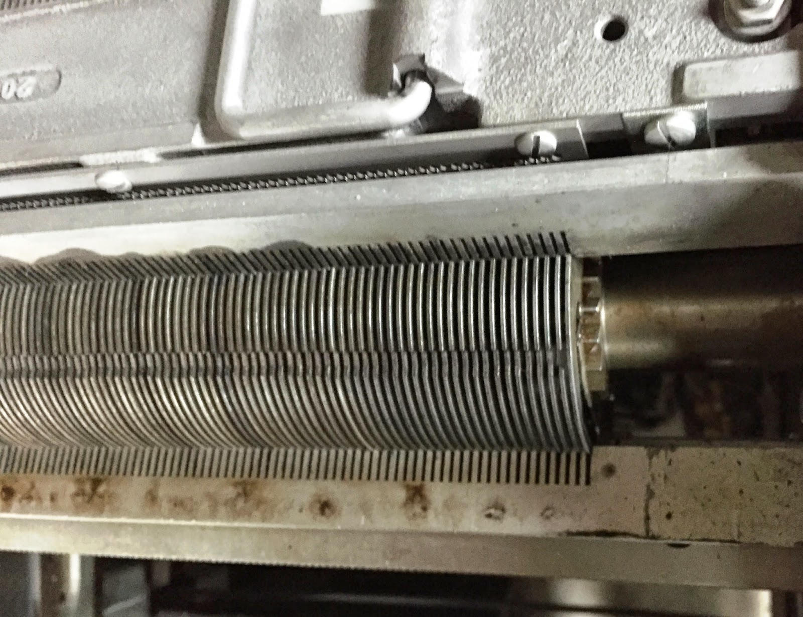
120 wheels are rotating by a gear driven from the printer motor. These wheels hang from a pivot point, allowing them to be forced forward closer to the paper on the platen. As the wheel moves forward, that motion is opposite to the turning direction from the drive gear, thus temporarily the print wheel appears to stop rotating just as the typeface slams into the ribbon and paper behind it. The wheel restores to its rest position by the force of gravity once it has bounced off the paper.

I removed the magnet assembly that holds the 120 print position solenoids, the actuating lever, the long horizontal bar and the pivoting latch. This fits up against the cams, restoring lever, detent lever and further forward, the print wheels on their pivots, but I removed the magnet assembly to work on all the parts methodically.

The pivoting latches were the first component I checked. Most of the print positions at the right side of a printed page were moving freely, but quite a few of the first 60 were frozen or very stiff. The worst of the latches were in the first 15 print columns, exactly where my test program attempted to print a known line. No wonder there was no detectable impression in most of the columns.

I used some Mobil 1 synthetic oil to flood the pivots and work all the pivoting latches, hoping to get them moving easily. After half a hour of oiling and hand movement, I had just a few, less than eight, that were still noticeably stiff. The other 112 were moving fine. I verified that my pushing on the downward rod just where the solenoid magnet will pull it - seeing that the pivoting latches were moving properly and easily as I did this.

I will take some more time for the oil to seep into the remaining eight pivot positions - they all move but with resistance and stick in the position they have when force is removed. The restoring spring that should pull them back to rest position can't overcome the high drag of the glue-like old lubrication and possibly a bit of rust. I will come back to these tomorrow and on subsequent days until they are all moving well.

I tried some of the cams, restoring levers and detent latches by hand, finding that these also were a mix of easily moving and frozen units. I will have to oil and manipulate the pivot points of these as well. I hope the dog mounted on the rotating cam is moving adequately, because if I need to work on those, I will have to take apart the entire set of cams from their shaft and rod. If the dogs work okay, then I won't need to do any disassembly.

The last area to inspect is the print wheel pivots, to test whether the print wheels can move forward if pushed by the print cam. I will look at this later when I begin oiling the restoring latch and cams.

My first look at the restoring latches shows major sludge drag and stickiness. This is going to be a long process to rehabilitate the printer, but I am confident I will eventually have it running well.

1442 CARD READER/PUNCH RESTORATION

I completed reassembly and some adjustments of the 1442. It continues to cause two kinds of problems - read checks on some cards and failure to slide fully into the cornerering station. The latter problem is just too much drag, as far as I can tell, since all the rollers and clamps are working properly. Further, it occurs even with the top cover of the station open, showing that it is drag on the face of the card against the brushed aluminum pathway.

I have cleaned, polished and cleaned these over and over. There is a possibility that it is drag with the punch station plate, since there is a bit of the metal base that can't be reached for cleaning due to a plate atop it that forms a narrow throat for card exit from the punch to the cornering station. I will take this apart, clean it more, and then adjust the throat upon assembly.

The read checks might be marginal light levels with the lamp, something that I can check out and adjust later. One annoying problem is that the individual condition lights that tell you what kind of Check has occurred are implemented with those miserable bare wire lamps hooked to the SCR, just like the main panel of the 1130. This means they break as you replace other bulbs, are touchy and darned hard to get an entire panel of them operating.

I did manage to get the Hopper Check lamp to work, but whatever is occurring to raise a check when I boot a card, is for one of the lamps that is NOT yet lighting. It would be helpful to know exactly what the reader believes is wrong.

SAC INTERFACE FOR ADDING PERIPHERALS TO THE 1130

I decided to put a 10000 pf capacitor across the base resistor between the 1130 SAC signal coming in and the transistor that will be switched, as a means of more rapidly removing the depletion charge and getting a faster shutoff of the otherwise saturated transistor. Without the capacitor in the circuit, I was seeing about 240ns delay between the drop of the incoming signal from the 1130 and when my transistor cut off and raised an pulse going out to the fpga. When I added the capacitor, my delay shrank to about 60 ns, which is quite acceptable in a 450 nanosecond cycle.

However, I see a phantom pulse rising about half 225 nanoseconds before the real one. Nothing on the incoming signal seems to match when it happens, thus this needs some additional study to determine why it occurs. It might be an induced signal from another nearby circuit switching, or caused by power rail or ground bounce. If it is the latter, I can add some more capacitors on the board to buffer power nearby each circuit.

I am going to think about this for a while, figure out some tests to confirm the cause, and then run tests until I am sure of the cause. The pulse is short, so I could filter in out in the fpga if necessary but that would add extra delay before I could recognize the logical condition mapped by the signal. Since I worked to remove delay, I don't want to be adding it back.

DATACENTER SHED CONSTRUCTION

The electrical system inside the shed is closed up, lacking only the connection to the overhead lighting I have yet to build and install. I took my multimeter out and verified the wiring including lack of shorts. Everything looks good in the wiring, Just need to anchor the panel, route and anchor the utility outlets, and anchor the light outlet.

Tonight I will tap the holes on another 7000 lumen 100W LED lamp array, putting the LED unit on heatsinks, adding a focusing lens and fan, then wiring to a constant current power supply which converts the 120V line power to a bit over 3A of DC current, which floats to somewhere over 30V due to the cumulative voltage drop of the LEDs in the array. I may be okay with a single lamp for the entire shed, but I can also use them in my family room to provide strong bounce lighting off the whitewashed cathedral ceiling. 

Friday, February 20, 2015

Put 1442 together, found issues with SAC Interface box, plus small tasks

1442 CARD READER/PUNCH RESTORATION

I lubricated the card feed clutch as I assembled it, then put it all together. I hand cranked it through a feed cycle and found that the mechanism hangs up when it is about 330 degrees around the cycle, bumping into some part of the clutch release mechanism which has to be tripped again to get the machine back to its 0 degree rest spot.

At this point, the reader is ready to be adjusted and tested some more. The feed clutch adjustments definitely have changed and need work, but it would be a very good idea to methodically adjust the machine from beginning to end. We found with the 1402 reader/punch on the 1401 systems at Computer History Museum, that only a complete sequenced set of adjustments would do away with the sporadic read checks and other problems that had been plaguing the systems for many months.

I closed it up to work on some other items first, but expect it won't be long before I am adjusting and testing this again. I have the manuals and appropriate tools to let me work my way through the adjustment process.

SHARING OF 1130 CARD DECKS

An enthusiast is using the programs and data that make music over a radio on an 1130, but converting them to another purpose. He spotted some apparent garbage in the deck of songs data, which lead me to re-read the deck and verify it with a second pass to compare the hole patterns.

However, there are still some suspect results, so I went to the ultimate source - the physical cards - and took a look at the line in question. Indeed, it was mis-read, twice the same way unfortunately so that it passed verification.

I will hand-annotate the file with the intended values from the cards then re-post it. Hopefully that will produce better results for the 1130 enthusiast. I found errors on one card from the initial reading but the corrected card is in the version I read then verified. The cards in question from that file all compared exactly to the physical cards in my hand.

SAC INTERFACE FOR ADDING PERIPHERALS TO THE 1130

I am still debugging the viability of the existing FMC Carrier S6 fpga board - trying to change enough to validate that it is working correctly. At this point, I see some life from the fpga when I directly load the bitstream, but it is not able to find and boot from its ROM when powered up.

My blinking light routine is displaying signs of life and I also see the reset button (BTND) working correctly. However, none of my lights on the expansion board or the set of 16 wired to other pins on the board are lighting.

Further, I still see severe delays on input signals from the 1130 appearing as outputs of my bus receiver circuit. Not sure if these are related, but the lack of operation of the LEDs that had been working when first constructed suggests some problem that might also be fighting input swings.

I am going to temporarily move one of the signal from the fpga and wire it to a TTL load, then scope the behavior of my receiver circuit. If the delay goes away, I can focus solely on diagnosing the fpga board. If, however, I still have almost 300ns of delay, most of a T cycle, then I need to redesign the interface electronics.

Before I did the test, I pulled up the spec sheet on my 2N3904 transistors used in the circuit and discovered to my horror that the transistor has a shutoff time of 240ns, exactly what I am seeing. These are inverted logic levels coming from the 1130 thus when the T6 cycle line is activated, the incoming voltage drops, cutting off the bias to the 2N3904 and the transistor should cut off, popping the output signal up to 3.3V. Which it does, including the 240ns delay to switch off. Yikes.

The problem is storage time of the transistor - since my circuit puts it into saturation when it is conducting, the charge has to diffuse away which is a slow process. If the circuit keeps the transistor out of saturation and barely operating, so that there is less charge to eliminate, making it switch off faster. A capacitor across the base bias transistor can remove the charge faster as well.

I will have to modify my receiver circuit or select a transistor with a much faster shutoff characteristic, breadboard it and wire it into the T6 signal path to observe its behavior. If it works as it should, I can lay out and build the 77 circuits necessary to replace my failed first attempt.

You can tell from this that I am new to electronics design, not even thinking about asymmetric transistor behavior or specifications that the circuit must meet. Once bitten, I will think about this for future designs, as an experienced electronics hobbyist probably would have. Sadly, the simulator web site I used to test the design wasn't giving me realistic timing, just voltage swings. I tested to see that it meet the voltage margins and logic level commitments, but not the speed of operation.

I still have issues with the fpga board plus extender - no lights and the inability to get it to correctly boot at power up from a ROM stored bitstream. I will do some debugging but now that I know the interface boards have to be replaced anyway, there isn't much time to be saved by preserving the cabling and pin assignments I made. Thus, the 'cost' to me of switching to a new fpga board isn't high.

I therefore just bought a ZTEX 2.01 board, which should arrive in 2-3 weeks. Even with shipping from Germany and a paypal surcharge, it was under $120 for the board. In the interim I will get the receiver and driver circuits behaving correctly.

DATACENTER SHED CONSTRUCTION

I added some Silicone sealant around the outdoor outlet box on the side of my house, as a belt and suspenders oriented safety margin in case water somehow enters the outdoor rated box. 

Progress on 1442 card reader reassembly and repair of Vectrex console

Back home from my trip by early afternoon and into the garage for a quick bit of work

1442 CARD READER/PUNCH RESTORATION

I was able to finesse the push rod into position, after finding an unusual angle where I could insert forceps holding the rod at precisely the right angle, then maneuver the other end slight into the upper socket.

At this point I am reassembling the card feed clutch, ensuring I get the right lubrication in place. I had to drive the taper pin out of the index marker and remove it, since the pin wasn't inserting all the way, plus it let me open up to address the lubrication.

REPAIR VECTREX CONSOLE FOR DIGITAL GAME MUSEUM

I did some more troubleshoot of the console, using my digital scope and the documentation. While I have a test cartridge now, I can't activate it until i can read the screen, a real catch-22, so I am proceeding 'blind' at the moment.

The Y signal looked similar to the images in the manual, but the X signal was decidedly odd. That would be consistent with the folding of images on screen, where lines of an object are not in their proper locations, inside seemingly randomly distributed on the screen.

The console uses a single digital to analog converter to produce analog signals for horizontal, vertical, brightness and sound. Since three work, I assume this is correct and moved forward in the circuitry. The X signal is directly routed, while the Y, brightness and sound signals are multiplexed through a mux/demux chip. The muxed signals work properly, so I skipped past this part as well.

LM347 Op Amps are used to integrate the voltages and move the beam on the screen, with the inputs to the op amp controlled by digital switches (a 4066 chip). I looked at the X signal circuits, which are one of the four opamp sections in the LM347 and two of the switches in the 4066. Since Y and other parts work, it is not a complete failure of any of those devices, but it could be a failed section. Passive devices like capacitors or signal connection (wiring/connector) problems could also be at fault.

Each op amp has one input hooked to a common 'zero reference' voltage which is shared among X and the other outputs which work correctly. The other input of the op amp comes from the DAC through a switch section of the 4066, turned on by the 'ramp' line from the microprocessor. This line also turns on the Y and remaining signal integrators, so it is presumed to work correctly, but if the digital switch is not operating or distorting the signal, it could impact the results.

At the end of a scan line, a different section of the 4066 digital switch is activated by the 'zero' signal from the microprocessor, which will short out or discharge the capacitors that are the feedback loop on the op amp. The capacitor feedback causes the op amp to be an integrator, sweeping the beam from one side to the other as the capacitor charges, then it is reset for the next line.

I will put my scope on the digital switch output and the gate signal, to see if it appears to change and do reasonable things. I plan to compare the working signal's switch, such as Y, with the failing X switch. I have to check both the reset ('zero') and the sweep ('ramp') switches, both for the X output and the reference behavior of the Y output. This means four sets of observations, which ultimately will finger a suspect or clear the digital switches.

After that, I can observe the ramp of the op amp circuit for signal X and the reference behavior of signal Y. This will help me determine if the op amp is correctly generating the sweep signal. Depending on the outcome, I can check passive components, e.g. the feedback capacitor, if they might cause the op amp output to be wrong.

All this requires several tiny attachments to hook onto individual legs of a DIP chip package without shorting to adjacent pins. I didn't have them at hand today, so will resume testing tomorrow with the ability to execute the tests above.

DATACENTER SHED CONSTRUCTION

I received some final parts needed for the wiring but didn't get out to the shed in time to do anything today. 

Tuesday, February 17, 2015

Traveling until Thursday, sourcing option to replace SAC Interface fpga board

I am on the road for a few days, back by Thursday afternoon. While I am away I don't expect to accomplish anything toward the 1130 project.

SAC INTERFACE FOR ADDING PERIPHERALS TO THE 1130

Since it is possible that my Digilent FMC Carrier S6 fpga board, at the heart of the interface box, has become inoperable, I did a bit of searching for alternatives. Digilent discontinued the board shortly after I bought it, making a direct replacement unlikely - none are on ebay at this time.

I need a high IO count board to support the 77 signals over the SAC interface plus a reasonable number of signals to whatever devices I control with the box. This rules out many of the more common development boards.

I did come across the ZTEX line of boards which will provide 100 input-output signals using a Spartan 6 fpga. The USB firmware and software on a PC is not the same as with the Digilent board, but it does appear it would fit the bill. At 89 euros, it is less expensive than the Digilent original.


Monday, February 16, 2015

Worked on shed, 1442 card reader, DMS card decks and SAC Interface debugging

1442 CARD READER/PUNCH RESTORATION

I began reassembling the feed clutch in the reader today. Things went smoothly until I hit two snags. First snag - the taper pin to hold the index wheel on the shaft didn't go in far enough, in my opinion, but it won't budge. Might need to drive it out and try a different way. Second snag - can't maneuver the pushrod behind the read clutch that connects the clutch actuator and the read mechanism above.

There isn't enough clearance to hold the pushrod in place. The read clutch lever can be moved by hand to open the gap and then close over the end of the rod, but I have to stand it in a ball socket at the bottom and pull the top of the pushrod under the clutch lever. The pushrod sits behind a metal casting, blocked by various mechanisms from any direct approach.

I can stretch fingers round from behind to touch the rod, but not much more. I don't have the dexterity to hold the rod and move the bottom end into a socket that I can't see because my hand blocks the view. Further, even if I get that end placed in the socket, I can't swing the top end to fit under the read clutch. A magician might have the extreme dexterity, or a much younger person, but I don't. I can't find an angle where any tools such as forceps can help me with this task.

Light was failing as the evening approached, a good time to pack up the reader parts and manuals. Once I am back from my business trip to Texas this week, I can resume putting the reader together.

READ TAPE OF 1130/1800 SOURCE CODE

I discussed the tape with Lyle, who has the equipment needed to convert the files, if readable, into transportable files I can pass back to Clare who loaned me the tape. If any of the files are general interest software and not just examples of client programs he wrote.

Lyle lives near me, making it easy to drop off the tape or have him stop by to pick it up when I am back from the trip.

SHARING OF 1130 CARD DECKS

After collecting all the binary phases from the DMS V2 R12 deck, I found that there were 72 missing phases, not just COBOL and RPG but also parts of the basic system. I will have to wait until I can extract the remaining files from disk onto either physical cards or directly to a PC file. IBM1130.org has source code listings, recreated from Microfiche and interpolation, but I will keep working until I can build the canonical distribution files.

SAC INTERFACE FOR ADDING PERIPHERALS TO THE 1130

I put my new digital storage oscilloscope on the SAC receiver circuits and monitored two signals. The basic oscillator of the 1130 and then the T6 time signal. The voltage levels looked good, but there was an unacceptable delay in the timing of the output pulse. T6 rises for a bit over 300ns at a time, but the output of my receiver circuit didn't start rising for about 200ns, dropping rapidly after the incoming pulse had dropped - not even giving me a delayed 300+ ns signal but instead something on the order of 100ns straddling the end of the incoming pulse.

Further, none of the lights wired to the FPGA display signals, they are all dark regardless of the slide switch positions on the fpga board. Further, the push buttons that should trigger interrupt levels yield no result on the 1130 or lights on the fpga expansion board. It looks like the fpga is not working and perhaps whatever is wrong with it is delaying the rise of the received signal.

I hope the fpga board didn't die - I bought it just before the maker stopped selling them, thus a replacement will be very hard to find. I will have to change the FPGA hardware to blink some lights as a startup sequence.

DATACENTER SHED CONSTRUCTION

Out to the shed in the morning to continue with the wiring process. Observant readers may have noticed that the heading on yesterday's entry was excessively optimistic, claiming completion of the wiring task. I didn't anticipate the pace at which I would crawl through the work.

I used UF (underground feeder - weatherproof cable), 8 ga which is huge, double the capacity needed for the machine but I selected it to minimize voltage drop. It is very heavy and harder to work with, making each connection and trimming a slow process.

When I wrapped it up, all that was left was to receive my 240V double pole 20A breaker, install it and close up the load center, plus some lighting work. I have the light wired up through the on/off switch but until I finish building the top lights I will use, I can't hook them into the top terminal box.  Otherwise, the inside of the shed is complete. I have a bit of silicone sealing to do on the outdoor enclosure box then it is ready once the circuit is hooked into the main circuit breaker panel.

Sunday, February 15, 2015

Finished internal wiring of data center shed, constructing 7000 lumen LED lights, plus work with card decks I recently read.

SHARING OF 1130 CARD DECKS

One member of the 1130 group on Google began working with the software to make the 1130 produce songs on a nearby radio, but he found that one of the data cards had suspect values. I had to dig out the deck again and reread it with verification in order to post the correct version.


DATACENTER SHED CONSTRUCTION

Needed another run to a shop for fine tuning the parts as I put together the wiring, Sunday morning, then worked solidly until the heat and exhaustion sent me indoors for a break. After fifteen minutes of down time, I was back out there working hard on the project.

Originally, I just copied the plug and socket used by the 1131 processor - but that is pure 240V - the two hot legs and ground - when I need the neutral wire brought out in order to deliver 120V for lighting, keypunches and other machinery.  After a quick purchase of the proper four lug plugs (L14-20), I could bring all the proper voltages out to the shed's load center where breakers power the 240V L6-20 socket for the 1131 system, plus 120V outlets and a 120V lighting circuit. 

Saturday, February 14, 2015

continued work on the shed and reading card decks

SHARING OF 1130 CARD DECKS

I finished all of the system load/reload decks, then moved on to some other decks in the trays. Several of the 1130 programs shared by IBM, such as card utilities, sort programs and sample decks to test the assembler/compilers, were read and prepared for sharing.

Breaking the system load/reload decks into phases is quite a bit of work as it yields about 200 separate binary files. I put in many hours carefully splitting and verifying the condition of the files. It should be ready to post tomorrow.


DATACENTER SHED CONSTRUCTION

It was a very balmy day, perfect for working on the shed power. I spent the afternoon outside doing this, including the need to take a run to a store to buy quite a few small items I realized I needed. This evening I put together the first 100W LED light array, producing a very strong light and no detectable heat during the short interval it was lit. 

Friday, February 13, 2015

Read all damaged cards, continuing with good cards in DMS V2R12 deck

SHARING OF 1130 CARD DECKS

I worked on the most damaged group of cards, slowly reading small batches as I straightened the leading edge damage. I ran into problems with a batch that had leading edge damage which was lighter than most of the group, but had trailing edge damage which tore the edge of the card at column 81, sufficiently to trigger spurious read checks. None of them had a tear far enough into the card to appear as a false hole in column 80, but the error checking logic of the Documation caught the damage.

This small batch of about 8 cards with trailing edge tearing is followed by a larger batch with only leading edge problems. I should be able to read the rest of the decks as long as I can get through these. At worst case these are cards I will have to hand-duplicate by using multipunch on the 029.

Late this afternoon I went back to the cards and, with great care, managed to get them all read successfully. I am well past the damaged section and can now rapidly read large batches at a time. Once I have the entire system deck captured, I can go through it and separate the binary files into the numbered phases.

My goal is to have all the parts of a system load or reload deck as separate files, which can be 'stacked' in the card reader of the 1130 simulator to run. As well, they can be combined as physical cards and run on a physical 1130 to load a real disk cartridge.

Thursday, February 12, 2015

Uploading DMS V2R12 cards, starting shed wiring

SHARING OF 1130 CARD DECKS

I spent a bit of time cleaning up the COBOL files, then moved on to read in and upload the operating system files to load DMS V2 R12, the latest that was made for the 1130 systems. Here I ran into card damage, which was unavoidable as we removed the cards from their original location in Kansas, because humidity had caused the cards to swell and become so wedged in their metal trays they couldn't be lifted out.

The only way that the crew could remove them to relieve some pressure was to pry some section of cards out of the tray, then redistribute them across more trays. This caused some damage to the sides of the card decks, with the most jammed trays holding the system load decks.

I have two sets of V2 R11 decks and only one V2 R12 deck. Each of the decks has a different section with damage to it. Here is an example of part of a V2 R11 deck, where the leading edge of the cards are so crushed that it is not possible to feed it through the reader.

Leading edge damage on card deck, rendering it unreadable
My prime target, the V2 R12 deck, has a damaged section but most of the damage is on the trailing edge, which I could straighten enough to avoid jamming. It did read well but there is a small portion with some front edge damage. I will have to feed these through one card at a time.
Trailing edge damage, but cards were able to be read successfully
Some leading edge problems, but can be carefully smoothed and individually read

Preserving historical computing information entails handling problems like these, which at worst case might require punching a duplicate of each card on the keypunch.

DATACENTER SHED CONSTRUCTION

I did some hunting and found a conduit with plenty of spare room, which solves the issue of having to open the wall inside my den to wire in the new EMT that will carry the power to my outdoor outlet box. I should be able to snake my new wire through the conduit and bring it out where I want to place the outlet box. The one puzzle to solve is how to insert the offshoot into the wire path without breaking the existing wires that run all the way through the house.

I made a run over to Orchard Supply Hardware since my newest order with Lowes appears to be stuck in the same groove - probably unlaterally cancelled by the store due to one item being out of stock, but that status never communicated to me. Further, the 800 number customer service sees the order as being processed (same as I see on the web site) which I am sure will persist for many days until it disappears mysteriously.

I began to drill and tap a heatsink for the 100W LED light array, but the cheap tap I bought didn't last more than two holes, in large part because the handle I used from a Harbor Freight tap/die set was so shoddily made that one of the two threaded handles wouldn't thread into the gripping block. With one handle falling out, it was hard to apply pure rotation, leading to the stress of the tape (which was American Vermont, a brand with somewhat higher quality control standards even if the taps come from the same factory). I am not in the mood to drive 25 minutes roundtrip just to buy a second tap, so this sits on the shelf until tomorrow or the weekend.

I do have almost everything I need to begin installing the outdoor outlet and the wiring (with cord to plug into the outlet) inside the shed. It will be sunny and in the mid 70s for the next five days, which is appropriate for doing the wiring and shed completion. 

Wednesday, February 11, 2015

Finishing reading all COBOL related cards, picked up supplies for wiring the data center shed

My day to volunteer at the CHM working on the 1401 systems, which cut down on my 1130 time a bit.

READ TAPE OF 1130/1800 SOURCE CODE

Still working out a date/time to get the tape read, but won't be long now.

SHARING OF 1130 CARD DECKS

I organized and cleaned up some of the COBOL compiler oriented decks I recently read. It became clear that there is some mixture of original distribution and updated files, based on a PTF that fixed some problems with COBOL. Later I found yet another section of cards labeled as a COBOL PTF. It will take a bit of sleuth work to figure out which are the latest files and whether I have a complete, usable system from card decks alone.

Since I also have disk cartridges with COBOL installed, I should be able to retrieve anything I don't have, but it will have to wait until there is a working 1442 card reader and punch or my emulated devices are working through the SAC Interface box that is still in debugging status.

COBOL was a licensed program, which makes it infeasible to publicly share this as I have been with other software I retrieved along with the 1130. I could run COBOL jobs for other people as long as it ran on one of my systems, but transferring the program to others seems forbidden.

DATACENTER SHED CONSTRUCTION

For some mysterious reason, when I arrived at Lowes to pick up the supplies I had ordered online, they found the order 'cancelled' with no way to find out why it happened. They speculated that some part which I ordered was not available in store, but claimed that I should have received a phone call yesterday to explain the cancellation. I am now left to re-order everything and then wait to see whether I get a call this time or perhaps the order will be fulfilled.

The parts of the order which are shipped from a warehouse have been fulfilled, based on emails confirming shipment. The store clerk promises that my credit card was not charged for the store pickup part of the order. I will need to verify this.

I placed a new order, but do see that my online account shows the order still in fulfillment, nothing there about cancelling a portion of it.  The second order produced a phone call telling me that they did not have the #10 green wire I was going to use for ground - I asked to pick up the remainder of the order and did so successfully this afternoon.

A few completer bits are on order, but if necessary I can stop in to one of the local stores for the parts. I have one or two decisions yet to make before I can start wiring up the outside outlet, but I certainly can wire the 'extension cord' and everything inside the shed, since the cord just plugs into the weatherproof outdoor outlet. 

Tuesday, February 10, 2015

Most of COBOL compiler read and being organized for uploading, plus beginning to wire up the shed

READ TAPE OF 1130/1800 SOURCE CODE

Another volunteer at CHM has contacted me, having systems able to read in the tape. He did warn me that NRZI tapes have a poor record of remaining readable years later, but we will try to retrieve it all. I have to call him tomorrow when I am over at the museum meeting with the 1401 team members.

SHARING OF 1130 CARD DECKS

This morning I battled through a few hundred more cards, getting them accurately scanned and uploaded. I also organized the files by the modules each would install, hoping to eventually verify that I have all parts of the compiler here. I found one PTF for the compiler mixed in with the other materials.

I also discovered I had been running with an old version of Brian Knittel's 1130 simulator. He had discovered the flaw in handling Overflow condition several years ago and corrected it. The latest version of the simulator, downloaded from ibm1130.org, worked just fine.

The late afternoon was when I next force fed cards in small batches through the reader hoping to get good clean reading and verification. I got to within 200 cards of the end of the deck by 3:30PM, close enough to stomach more verify checks and other problems in order to finish up the compiler.

By five I had all of the cards marked Cobol, but I found a batch of cards inside the tray used to load the system on a disk, marked Cobol Phases, which I also need to read as they are probably the remainder of the compiler. That was a block of about 800 cards. I managed to read about a third today.

DATACENTER SHED CONSTRUCTION

I began construction of the LED lighting modules for the shed (and also for my den) - these are 100W LED arrays mounted on heatsinks and fronted by spreader lens,. In the den they are mounted up on cross beams replacing fluorescent lights, bouncing up off the whitewashed cathedral ceiling to give general illumination throughout the room. In the shed, they will provide bright direct lighting downward from cross beams, positioned at a couple of points where good light is most important.

I also began detailed plans for the power distribution inside the shed, in order to buy the supplies necessary for construction. I will pick up most of the parts today, but the wire itself is coming by UPS and will take a few days. 

Monday, February 9, 2015

Uploaded diagnostics, loaders, some utilities and began on the COBOL compiler

READ TAPE OF 1130/1800 SOURCE CODE

My tape drive is also 1600/6250 BPI but unable to read 800 BPI tapes. I do have a lead on another volunteer at CHM who should a system that can read the tape.

SHARING OF 1130 CARD DECKS

At lunchtime I read in, tested and uploaded the diagnostic decks and related loaders. In addition, I uploaded the standalone DCIP (disk utility). The first diagnostic I ran on the 1130 simulator, the CPU function test, discovered some flaws in the simulator itself.

The Overflow condition of the 1131 is reset several ways, one of which is supposed to be any test of the condition itself. Thus, after a test such as BSC O (Skip if overflow not set), the condition should be reset if it was set before. On the simulator, it stays on after the test. I entered some code on my 1130, which turned it off after the BSC O ended, consistent with the Functional Characteristics manual.

I began to read in the COBOL compiler in order to share that with the group, but am finding the cards challenging to read. The surface is slick and the cards a bit warped due to moisture. I can't read more than about 100 cards at a time if I have any hope of getting them read and a successful verify pass afterwards. Often the verify fails but the cards are good, but sometimes the first read is bad which becomes clear when the same verify error crops up multiple times.  I processed about 500 cards before setting the task aside.

I made it through another few hundred cards in the early evening, until overcome by the tedious work of scanning the same small groups of cards a dozen times or more. At this point I am halfway through the compiler cards.

Sunday, February 8, 2015

Shed dry during rains, read cards and tapes to upload, and published new beta of keypunch PC side software

NEW KEYPUNCH INTERFACE DEVELOPMENT

I created a standalone executable version of the PC side software at the new beta level, allowing users to easily install and test it without having to install Python or its modules on their machine. I then updated the user guide to include these changes and pushed it up to Github

READ TAPE OF 1130/1800 SOURCE CODE

I went over to my friends house with the tape of source code, we put it on his tape drive to read in what we could. Unfortunately, the tape is recorded at 800 BPI, which means NRZI encoding. All four drives my friend owns, of several makes, only read PE (1600) and faster (e.g. up to 6250BPI).  I will have to see if my IBM tape drive will read 800, or look for another system to read it on.

I did help my friend work on his newly bought Documation card reader. We discovered that the motor which drives the blower and vacuum pump has a seriously bent shaft, making the pulley on it wobble unacceptably. It made a horrible noise and threw the belt when he first tried running it. Amazingly, we found the exact same motor on ebay for $25 (shipping extra) and he bought it immediately.

SHARING OF 1130 CARD DECKS

I read in the remainder of my boxes of shareware programs and line printer art, cleaned up all that were usable and uploaded them. I found a program to use the emissions of an 1130 to play songs over an AM radio held near the processor. Once i get it running I will video the results and post.

I began reading in and saving the binary decks including diagnostics and stand alone utilities. It is going to be a slower process with the system decks, as they are mixed ASCII and binary, each of which I want to upload in its proper encoding.

DATACENTER SHED CONSTRUCTION

After a series of very large and sustained rainstorms. I inspected the inside of the shed to find it completely dry inside. Not a drop of water visible nor any signs that water was in there earlier. Since the doors, misaligned as they are cosmetically, do close and they keep the water out, I am going to finish the other anchor bolts to hold this firmly down and begin outfitting it for power and light.

The power will be via a heavy duty cable with plug that will be temporarily inserted in an outdoor socket on the side of my house - this keeps the shed legal whereas permanent wiring would require a permit. I will bring in four wire power (240 with neutral and ground, giving me both 120 and 240 power). I have some of the materials I need to complete the power and lighting, but not all of them.

I do have some 100W LED lighting units to install for illumination. These consume 100W, which makes them much, much brighter than a 100W incandescent lamp, requiring thermal grease, heat sinks and fans to keep the LED junctions at a reasonable operating temperature.