I have been completely tied up with several non-computer projects. I had my driveway and walkway replaced with pavers, a flagstone patio added and stone veneers added across the bottom 2' of the front of my home. In addition, I am building the 16' Pirate Ship bar and other props for a fundraiser in October.
Thursday, August 31, 2017
Short hiatus attending to other tasks
DISTRACTIONS AND OUTSIDE PROJECTS
I have been completely tied up with several non-computer projects. I had my driveway and walkway replaced with pavers, a flagstone patio added and stone veneers added across the bottom 2' of the front of my home. In addition, I am building the 16' Pirate Ship bar and other props for a fundraiser in October.
I have been completely tied up with several non-computer projects. I had my driveway and walkway replaced with pavers, a flagstone patio added and stone veneers added across the bottom 2' of the front of my home. In addition, I am building the 16' Pirate Ship bar and other props for a fundraiser in October.
Saturday, August 26, 2017
Display repaired for Digibarn Alto, first test of disk emulator tool
DIABLO EMULATOR VERSION OF ALTO DISK TOOL
The three grids have potentials of up to 1000V so we proceeded carefully in our testing! I have an old vacuum tube voltmeter with a probe good to 30,000V (implements a large voltage divider and has an impressive plastic shield to keep hands away from high tension). It showed zero volts on all three grids.
Studying the schematic gave us a few places to probe between the flyback transformer winding that delivers 600V as short pulses during each horizontal retrace and the other circuitry, some that doubles up to about 1000V and others that generate -100. We found that a small incandescent bulb on the PCB was the fault!
The design routes the short retrace pulses of 600V through this bulb, a 28V 40ma mini lamp, depending on the shift in resistance of the filament from cold to warm to provide a kind of current regulation. The bulb had a lead cracked off where it entered the glass envelope.
Marc was able to reattach a lead to it, using his binocular microscope, a soldering iron and lots of patience. With it installed the monitor worked beautifully.
We then installed the four power supplies into the Alto and began inserting cards into the backplane. Unfortunately, the machine lacked one card, the memory address terminator board, and needs several cables that run between various boards. We didn't have time to proceed any further on this machine.
I hooked the emulator up to the Alto but it did not boot from the virtual disk. We did this very late in the test session, when there was not enough time to start scoping signals. Therefore I have no idea what may be going wrong - whether it is electrical, a chip malfunction on my daughter card, a logic flaw in the FPGA or something else.
I have to wait for the next session, which Marc may not be able to schedule for a few weeks as he attends to other projects. Since our Alto is in his basement, no work can proceed except when he can host us.
RESTORATION WORK ON DIGIBARN ALTO
At our last session, we found that the Display for the Alto owned by Bruce Damer/Digibarn was displaying black but seemed to have scan and an image in the instant when it is powered down. My suspicion was that one or more of the three grids had a potential that was blocking the electron stream, but as various capacitors discharged during power-down the stream could temporarily make it through.I have to wait for the next session, which Marc may not be able to schedule for a few weeks as he attends to other projects. Since our Alto is in his basement, no work can proceed except when he can host us.
RESTORATION WORK ON DIGIBARN ALTO
The three grids have potentials of up to 1000V so we proceeded carefully in our testing! I have an old vacuum tube voltmeter with a probe good to 30,000V (implements a large voltage divider and has an impressive plastic shield to keep hands away from high tension). It showed zero volts on all three grids.
Studying the schematic gave us a few places to probe between the flyback transformer winding that delivers 600V as short pulses during each horizontal retrace and the other circuitry, some that doubles up to about 1000V and others that generate -100. We found that a small incandescent bulb on the PCB was the fault!
The design routes the short retrace pulses of 600V through this bulb, a 28V 40ma mini lamp, depending on the shift in resistance of the filament from cold to warm to provide a kind of current regulation. The bulb had a lead cracked off where it entered the glass envelope.
Marc was able to reattach a lead to it, using his binocular microscope, a soldering iron and lots of patience. With it installed the monitor worked beautifully.
We then installed the four power supplies into the Alto and began inserting cards into the backplane. Unfortunately, the machine lacked one card, the memory address terminator board, and needs several cables that run between various boards. We didn't have time to proceed any further on this machine.
Thursday, August 24, 2017
Small mod to the disk emulator board and work on the pirate ship bar
DIABLO EMULATOR VERSION OF ALTO DISK TOOL
FUNDRAISER PROP - PIRATE SHIP BAR
I worked a bit on my gimmicks for the prop. I plan to have a lifesize photo of Johnny Depp's head as Cap Jack Sparrow pop up from behind the ship facade and bob back out of sight. I have the actuator and just received my 'head'.
The cannons will flash with a 1200 lumen high intensity LED, which I tested at almost full power using my current limiting bench power supply. It is plenty bright even for daylight, mounted inside the cannon, and should be spectacular at night time when most of the fundraiser occurs.
I also received the fog generating fluid to put in the fog machine, which I fired up as a quick test of the volume and quality of the fog produced. It seems okay, but I am still figuring out the machine, whose output was a bit erratic. I will do more testing once the ship is built.
Well, I discovered that the emulator board I built has a defect. It does NOT ground pin 21 of the FPGA connector, which it should to indicate to the logic that this is the emulator daughter board. I will add a short wire to fix the board.
I went through the logic and removed all the instrumentation/test related code from the VHDL - the buttons to trigger updates or writes from the test generator and the use of the sense switches to set seek addresses. A bit of other cleanup as well and it was ready to produce the version I will use for testing tomorrow on the Alto. |
| Jumper added to ground pin 21, identifying this as an emulator board |
FUNDRAISER PROP - PIRATE SHIP BAR
I worked a bit on my gimmicks for the prop. I plan to have a lifesize photo of Johnny Depp's head as Cap Jack Sparrow pop up from behind the ship facade and bob back out of sight. I have the actuator and just received my 'head'.
 |
| Cardboard head to pop up (actually a flat mask |
 |
| My high intensity LED operating at about 70% of full power |
Cable and board completed for Diablo emulator disk tool for Alto
DIABLO EMULATOR VERSION OF ALTO DISK TOOL
I have to finish the cable that will hook between the Xerox Alto and my emulator, verify all the wiring and function on the emulator daughter card, then I will be ready to haul this over and use it with our Alto.
The IDC header connector, two rows of 20 pins, will clamp onto the cable end and plugs into my daughter card. That card converts the +5V input signals from the Alto controller to the 3.3V levels used with the Digilent Nexys2 FPGA board. It also takes 3.3V outputs from the FPGA board and drives relatively high current at TTL levels to the controller card. Finally, it implements the end of cable termination with resistor pairs that match the Diablo drive terminator plugs.
I verified that the pins on my board match the cable signal lines 1 - 40 and the connector at the far end. This means that once I have the IDC connector installed and my board is electrically traced for its validation, I should be ready to cable up to an Alto.
By dinnertime, the connector was installed on the cable and checked out. All that remained was to trace each signal line between the IDC connector and support chips, then each line between the FPGA input connector and the chips.
The IDC to chip links were all proven good by 8PM, when I turned to checking the FPGA connector to chip lines. By bedtime I completed that task too. I believe this is ready to test on a real Alto, probably this Friday.
I have to finish the cable that will hook between the Xerox Alto and my emulator, verify all the wiring and function on the emulator daughter card, then I will be ready to haul this over and use it with our Alto.
 |
| Cable that attaches to Alto disk controller card |
 |
| Other cable end, after ground plane peeled off, before connector attached |
 |
| Daughter card to do level translations and terminate the cable |
By dinnertime, the connector was installed on the cable and checked out. All that remained was to trace each signal line between the IDC connector and support chips, then each line between the FPGA input connector and the chips.
 |
| Cable attached to emulator daughter card |
Tuesday, August 22, 2017
Diablo disk emulator testing completed, plus pirate ship design and fabrication begins
DIABLO EMULATOR VERSION OF ALTO DISK TOOL
My explorations this morning proved that the test generator is outputting the correct stream of bits. I then moved on to the logic that produces the WriteDataClock signal, to determine what stream comes out of it and compare to the test stream. Each such step requires re-synthesis thus incurs a 20-30 minute delay.
The WriteDataClock signal looks wonky, although the testgenerator values seem right. I made some tweaks to the logic that converts the testgenerator bits into the NRZI encoded signal and synthesized once again. I could then see that the WriteDataClock signal is correct but the recovered bittrain is wrong.
Onward I moved to instrument the logic that entrains on the clock pulses of the WriteDataClock signal and extracts data values from the spaces in between. After a suitable pause to synthesize I was ready to run the next experiment.
I can see the logic incorrectly detecting data bit values, but it will take a careful listing of the timing of all the signals and state machines before I can determine the flaw and repair it. The key is in the two state machines - one entraining and tracking clock pulse, the other detecting data pulses. One of these, or their interaction, is misbehaving.
I found it! A window vulnerability that would extend the time in the data extraction FSM in certain circumstances to cause it to misregister spurious 1 data values. With that repaired, the logic handled the updates perfectly, both to alter just the data record and to alter both label and data record. I think the checksum testing worked properly as well, but to be certain, I prepared some signals to watch with the logic analyzer.
Also, I tweaked the testgenerator to put in some different values, particularly for the header record, so that I could do a test where the entire sector is written. The synthesis took a while, but I was pretty confident in the outcome.
The results were perfect. My update logic works fine for any time the WriteGate logic is turned on somewhere in the space between the records (or in the preamble for the first - header - record). As far as I can tell without hooking this to an Alto, it seems ready to provide an emulated disk drive.
FUNDRAISER PIRATE SHIP DEVELOPMENT
My wife and I are building props for a fundraising event at Villa Siena; this year's theme is Pirates & the Caribbean. The bar will be a 16' long pirate ship, 4-8' high not counting the mast/sail. It will be a facade, not three dimensional, but I will have several 'cannons' protruding from the side.
Inside the cannons will be bright LEDs to simulate cannon fire, along with a continuous performance of the song from the disney theme ride. Too, I will have a pirate head peeking above the deck and smoke from the cannons and down low as 'water'.
I have most of the gear on hand and began working out my wiring design. I will use a constant current power supply set to .7A to deliver the voltage to each LED. These will be wired through a bank of relays, one per cannon, that I can activate with an Arduino program. The program will also produce the cannon fire sound, independent of the song playing through another small MP3 device.
There are a host of other props, including pier pylons with ropes, palm trees, treasure chests and barnacles. We also found a life sized skeleton that we can sit on a bench and dress with a bandanna, eyepatch and pirate hat. Atop its shoulder is a correctly proportioned parrot skeleton that will also be clad in hat, bandanna and patch.
My explorations this morning proved that the test generator is outputting the correct stream of bits. I then moved on to the logic that produces the WriteDataClock signal, to determine what stream comes out of it and compare to the test stream. Each such step requires re-synthesis thus incurs a 20-30 minute delay.
Onward I moved to instrument the logic that entrains on the clock pulses of the WriteDataClock signal and extracts data values from the spaces in between. After a suitable pause to synthesize I was ready to run the next experiment.
I can see the logic incorrectly detecting data bit values, but it will take a careful listing of the timing of all the signals and state machines before I can determine the flaw and repair it. The key is in the two state machines - one entraining and tracking clock pulse, the other detecting data pulses. One of these, or their interaction, is misbehaving.
I found it! A window vulnerability that would extend the time in the data extraction FSM in certain circumstances to cause it to misregister spurious 1 data values. With that repaired, the logic handled the updates perfectly, both to alter just the data record and to alter both label and data record. I think the checksum testing worked properly as well, but to be certain, I prepared some signals to watch with the logic analyzer.
Also, I tweaked the testgenerator to put in some different values, particularly for the header record, so that I could do a test where the entire sector is written. The synthesis took a while, but I was pretty confident in the outcome.
The results were perfect. My update logic works fine for any time the WriteGate logic is turned on somewhere in the space between the records (or in the preamble for the first - header - record). As far as I can tell without hooking this to an Alto, it seems ready to provide an emulated disk drive.
FUNDRAISER PIRATE SHIP DEVELOPMENT
My wife and I are building props for a fundraising event at Villa Siena; this year's theme is Pirates & the Caribbean. The bar will be a 16' long pirate ship, 4-8' high not counting the mast/sail. It will be a facade, not three dimensional, but I will have several 'cannons' protruding from the side.
Inside the cannons will be bright LEDs to simulate cannon fire, along with a continuous performance of the song from the disney theme ride. Too, I will have a pirate head peeking above the deck and smoke from the cannons and down low as 'water'.
I have most of the gear on hand and began working out my wiring design. I will use a constant current power supply set to .7A to deliver the voltage to each LED. These will be wired through a bank of relays, one per cannon, that I can activate with an Arduino program. The program will also produce the cannon fire sound, independent of the song playing through another small MP3 device.
There are a host of other props, including pier pylons with ropes, palm trees, treasure chests and barnacles. We also found a life sized skeleton that we can sit on a bench and dress with a bandanna, eyepatch and pirate hat. Atop its shoulder is a correctly proportioned parrot skeleton that will also be clad in hat, bandanna and patch.
 |
| Before hats, eyepatches and bandannas |
Debugging the update/write logic for the Diablo disk emulator for the Alto
DISK EMULATOR VERSION OF ALTO DISK TOOL
I found and cleaned up a couple of places where the various FSMs could be stepping on each other for memory access. With that repaired, I retested. The flaw uploading memory to the file was fixed. I also verified that when I pushed the buttons, I would "rewrite" the label+data or just data records.
Unfortunately, I didn't get the data bit values I expected from the updates. Further, the logic reported checksum validation issues, which totally makes sense. It left the header records alone and when I used the button to update only the data records, the label records were also untouched.
I have to work out the best diagnostic traces to emit, to pick up a hint with the logic analyzer as to why I am not correctly detecting the words I expect. The data patterns don't look like the result of an error in the deserializer that shifts the bits around. The patterns are consistent across runs.
For example, the last word of the data record should be x5462, the output of the test generator, but I see xE440 instead. I need to watch the entrainment and sync process, then the deserialization, to found out whether I am picking out the bits properly.
The logic analyzer was wired, configured and the board set up for testing. Right away, I saw the deserializer tossing out words (that matched what was written into memory), but having no relationship to what I was emitting out of the test generator.
I made some tweaks to look at other signals and gave the logic a quick lookover. I can see that the deserializer is telling my UpdateRecord machine that it has accumulated a word after achieving sync. The word it presents is the same value xE440 that I see in memory.
This points me at the deserializer operation as the malfunctioning process. I did a dig through the logic analyzer traces to see whether I could spot the problem. It jumped out at me, particularly when I set up the scope to trigger on my update of the data record and display the WriteDataClock signal I was producing.
My test generator is not producing good output. Specifically, it is generating the sync bit followed by xE440 which is exactly what my deserializer picks up. The fault is in the test generator. Now I can focus on that logic and do some simulations to find the bug.
I found and cleaned up a couple of places where the various FSMs could be stepping on each other for memory access. With that repaired, I retested. The flaw uploading memory to the file was fixed. I also verified that when I pushed the buttons, I would "rewrite" the label+data or just data records.
Unfortunately, I didn't get the data bit values I expected from the updates. Further, the logic reported checksum validation issues, which totally makes sense. It left the header records alone and when I used the button to update only the data records, the label records were also untouched.
For example, the last word of the data record should be x5462, the output of the test generator, but I see xE440 instead. I need to watch the entrainment and sync process, then the deserialization, to found out whether I am picking out the bits properly.
The logic analyzer was wired, configured and the board set up for testing. Right away, I saw the deserializer tossing out words (that matched what was written into memory), but having no relationship to what I was emitting out of the test generator.
I made some tweaks to look at other signals and gave the logic a quick lookover. I can see that the deserializer is telling my UpdateRecord machine that it has accumulated a word after achieving sync. The word it presents is the same value xE440 that I see in memory.
This points me at the deserializer operation as the malfunctioning process. I did a dig through the logic analyzer traces to see whether I could spot the problem. It jumped out at me, particularly when I set up the scope to trigger on my update of the data record and display the WriteDataClock signal I was producing.
My test generator is not producing good output. Specifically, it is generating the sync bit followed by xE440 which is exactly what my deserializer picks up. The fault is in the test generator. Now I can focus on that logic and do some simulations to find the bug.
Sunday, August 20, 2017
Test generator installed in disk emulator version of disk tool, starting to debug
DISK EMULATOR VERSION OF ALTO DISK TOOL
I updated my built-in test generator, which had been built to create input for the ReadClock and ReadData lines while I was testing the disk driver version. It now produces input for the WriteDataClock line.
I also added logic that will turn on the WriteGate signal for a portion of each sector when I push either of two buttons on the fpga board. One button will begin writing only for the data record, while the other will write during both the label and data records.
I wired these generated signals to the inputs they will drive and began some testing. I first loaded the board with the XMSMALL disk image, ran without any updates and verified that the image in memory remained untouched. Second, I would triggered an update of the data records of sectors, uploaded the memory image and checked to see if I had altered just the intended words.
The file upload from the memory is not working properly. I can see the ReadClock and ReadData produced by the disk drive, which match the image I downloaded, but when I upload I get zeroes. I can see the WriteGate condition flick on when I push the buttons, but without a way to pull the memory up to a file, I can't determine whether it worked properly.
I did make changes to the logic involved in memory access in order to add in the sector updating/writing logic, so that is the first place to look. I might need to organize some diagnostic output that can be captured on the logic analyzer if I don't see anything obvious.
I updated my built-in test generator, which had been built to create input for the ReadClock and ReadData lines while I was testing the disk driver version. It now produces input for the WriteDataClock line.
I also added logic that will turn on the WriteGate signal for a portion of each sector when I push either of two buttons on the fpga board. One button will begin writing only for the data record, while the other will write during both the label and data records.
I wired these generated signals to the inputs they will drive and began some testing. I first loaded the board with the XMSMALL disk image, ran without any updates and verified that the image in memory remained untouched. Second, I would triggered an update of the data records of sectors, uploaded the memory image and checked to see if I had altered just the intended words.
I did make changes to the logic involved in memory access in order to add in the sector updating/writing logic, so that is the first place to look. I might need to organize some diagnostic output that can be captured on the logic analyzer if I don't see anything obvious.
Saturday, August 19, 2017
Logic complete for disk emulator version of Alto disk tool
DISK EMULATION VERSION OF ALTO DISK TOOL
I ran quite a few simulations of the logic to watch the WriteDataClock line, get in sync with the clock pulses (entrainment) so that it can detect data bits, detect data bits properly, and switch on the sync state when it sees the first non-zero data bit value.
It worked well for various offsets, random variations, slower and faster rates. That code is locked into place. I turned to the logic to drive the deserialization - picking parallel 16 bit words from the serial bit stream encoded in the WriteDataClock input from the Alto.
It has to stay on the word boundaries, find the right pattern and signal when each word has been extracted. Those words are picked up and written to memory during write or update operations on the disk, plus an extra checksum word is sent at the end of a record which allows us to detect if we mangled the data stream.
This too needs a simulation that can present a longer bitstream after the sync word, more than two entire words, with a mix of 0 and 1 bit values. After I put that together, I ran the simulation, fine tuned the logic and ended up with machinery that will successfully look for the sync word and then extract words from the stream as long as it is allowed to stay in the synchronized state.
Moving up one layer in functionality, I need to finish the UpdateRecord machine that handles writing one record of a sector. All it has to do is:
I ran quite a few simulations of the logic to watch the WriteDataClock line, get in sync with the clock pulses (entrainment) so that it can detect data bits, detect data bits properly, and switch on the sync state when it sees the first non-zero data bit value.
It worked well for various offsets, random variations, slower and faster rates. That code is locked into place. I turned to the logic to drive the deserialization - picking parallel 16 bit words from the serial bit stream encoded in the WriteDataClock input from the Alto.
It has to stay on the word boundaries, find the right pattern and signal when each word has been extracted. Those words are picked up and written to memory during write or update operations on the disk, plus an extra checksum word is sent at the end of a record which allows us to detect if we mangled the data stream.
This too needs a simulation that can present a longer bitstream after the sync word, more than two entire words, with a mix of 0 and 1 bit values. After I put that together, I ran the simulation, fine tuned the logic and ended up with machinery that will successfully look for the sync word and then extract words from the stream as long as it is allowed to stay in the synchronized state.
- watch WriteDataClock for the sync bit
- extract each word from the deserializer
- writing the word to the proper place in memory
- accumulate the running checksum with each word
- compare the extracted checksum to the calculated one
This machine is only triggered from the higher level UpdateSector machine if the WriteGate signal is turned on while the GenerateSector machine is in the preamble phase of a record. The UpdateSector machine follows GenerateSector in lockstep, but is setting up the addresses for memory control and counts that will be needed if the WriteGate goes on to update each record.
By late afternoon I had all the logic in place, but as yet untested. The emulator should work properly at this point. There is only one area where I deviate from the behavior of a real Diablo drive and that is when the Alto is writing to the drive, a real drive will echo the data back on ReadClock and ReadData, but I don't. One might have a diagnostic program that attempted to look at the ReadGate enabled stream while it is writing with WriteGate on, but due to a time delay this is nontrivial to do.
I began to mull ways I could simulate or build in a testdriver to do some testing without having a real Alto connected. This took some time. My earlier testdriver for testing the disk driver produces bits that look like the serial stream in from a disk.
I have to blend it to a shared clock and data line, to be routed into the WriteDataClock input. Too, I need a control that lets me trigger the three flavors or writing - write entire sector, read header then update label + data, or read header + label then update data.
I won't finish this today but I am planning the necessary changes and should get this together tomorrow. This is a internal test generator, only being used for debug.
Friday, August 18, 2017
Xerox Alto work, donated Hawley mouse, and work on some other components
XEROX ALTO RESTORATION
We received a donation of a Hawley (mechanical) mouse for use with our Alto system, provided by Dave Redell. It was very clean cosmetically, but had a few small internal issues. This mouse turns mechanical encoder wheels with multiple 'fingers' riding on the wheels, but one of the fingers was bent out of contact.
The finger was easily corrected. We then tested the mouse operation and found it failed to work well with horizontal movement, but was great when moved up and down. Some investigation inside the mouse turned up some stuck bearings. They responded well to a light machine oil and some manipulation.
The mouse is a delight, smooth moving and very precise. The major downside of these mice is lint and dirt, which clogs the inside after it is used awhile. Regular cleaning will address this problem.
We turned our attention to the other Alto, belonging to Bruce Damer and his Digibarn collection. Having finally repaired the power supplies, we did a full load test on all of them. Some of them had capacities of 12 to 15 amperes, but the main 5V supply we tested to the 60A capacity of Marc's HP Electronic Load.
Next up was the CRT. The display was actually wired to hook to a more modern Xerox system, such as a Dandelion, which uses a remote peripheral bus that is completely incompatible with the Alto. Ken Shirriff investigated to find that the new protocol is implemented by a board that hooks to the original vertical, horizontal and video lines which are what our Alto wants.
Ken built a cable that interfaced the new display to the original Alto display connector. We hooked up the CRT test tool loaned to us by the Living Computer Museum. The screen stayed black, but when the power switch is flipped off the pattern from the test tool is visible, bright and clear, as the monitor image collapses.
We moved the monitor to the workbench and began tracing signals to find the fault. First up, we monitored the display sweeping and doing flyback. Next we traced the video input signal through the amplifier stages all the way to the connector that leads to the CRT itself. The signal is fine, which means we have a more subtle problem that is blocking the electron stream from hitting the phosphors on the tube face.
We ran out of time, but the next time we get together we will trace through the voltages and signals on the various grids and other CRT elements. Likely we will find one of the grids is markedly more negative than the prior one, due to some component issue. We expect that when the power switch is flipped off, some voltages decay faster than others, unblocking the stream for a brief time so that we can see the pattern on the screen.
We looked over three disk drives we have on hand (other than the drive in the Alto). All three have crumbling foam at the point where clean air is forced through the cartridge. Crumbling bits of foam will lead to head crashes, as we have already experienced. Next session, we have to clean and replace these foam gaskets.
Thursday, August 17, 2017
Disk emulator role of Alto tool now handling read operations, working on write/update
DISK EMULATION VERSION OF ALTO DISK TOOL
I have a completely populated and wired board for the emulator role, consisting of the circuitry to shift levels between the FPGA's 3.3V needs and the TTL relatively high current signals between the Alto and a real Diablo drive. What is still to accomplish is to build the female socket into which the Alto's cable will plug.
As expected, aligning to an async incoming stream of WriteDataClock, determine which pulses are the clock pulses and attaining synchronization is difficult. First is entrainment, where I determine the start of the 600ns bit cell. This begins when WriteGate goes active and depends on the fact that the preamble is many words of all zero data bits.
After entrainment is achieved, the logic has to accommodate jitter, based on the real edges, to stay entrained. That means we can pick off data bits reliably. Sync occurs when the first '1' data bit arrives. The next bit cell is the start of the data words of a record. When the checksum has been read and compared, we drop sync but keep entrained unless WriteGate drops.
With the entrainment and deserializing logic built, the challenge was testing without a real async and jittery input stream. I turned to the Xilinx simulator and attempted to create a pulse pattern with plenty of jitter and edge cases, to see if my logic will properly entrain and extract data bit values as well as detect a sync state.
I am now working through the logic and the simulator results, fine tuning to yield reliable entrainment and then sync detect. It is now early evening and nearly time to shut down for the day. Since I have a session with the Alto tomorrow, the weekend is when the next burst of progress can take place.
Today I set up and validated the basic engine producing the ReadClock and ReadData signals that are emitted by the drive whenever the ReadGate is active - the disk continually rotates under the head and the bit patterns from each sector sequentially stream out through those signals.
Following that, I modified the logic to become the generator process that will build up a sector image. This begins at each sector mark and
- counts off words of zero as preamble padding
- emits a sync word for each of the three records
- fetches data from memory to load the serializer for each word of the record
- calculates a running checksum of the words for each record
- loads the serializer with the checksum value at the end of the record
- emits words of zero as a postamble padding
- cycles bad to do preamble, sync, data words, checksum and postamble for the next record
Since a sector is comprised of three records - header, label and data - there is an 'inner' process to actualy emit the preamble words, sync, data words, build the checksum, send out the checksum and produce the postamble. It is called from the master generator process, given a count of words, memory starting address, and preamble count.
The key to everything is the serializer, which is loaded with words by the generate record logic at the appropriate time. It gets a request for the new word from the serializer after that process has shifted out each bit of the word to become ReadData pulses. The generate record logic just passes the appropriate new word to the serializer - zeros for padding, a sync word pattern, memory contents for data words and the checksum result - as the requests for new words arrive.
I worked out from the serializer, making sure it was shifting out bits when the ReadClock pulse occured and had it ready for the ReadData pulse. Too, it had to issue the request to load a new word when it output the final data bit.
With the serializer proven out, I then debugged the record generator, ensuring it fed the right values into the serializer. The scope shows a plausible stream of bits for the sectors but just to be sure, I will set up triggering for one specific sector number and carefully inspect the bit patterns to be sure they match what should be read.
These match the patterns I should see, including proper checksums. I varied the cylinder using seeks and altered the head between upper and lower surface, further validating that the data patterns being emitted are correct.
With the bits streaming out of the emulator properly, available for the Alto to do a read, it was time to build up the logic that supports writing or updates. When the Alto turns on the WriteGate signal, it will be producing clock and data pulses on the WriteDataClock signal line.
FSMs must do a sync to the incoming stream to establish the clock vs data boundaries, since the input from the Alto is a combined signal that always pulses for clock bits but the span between clock bits will pulse only for a 1 value bit. This will occur when the GenerateRecord process is beginning its sync word phase, if WriteGate is on.
Sync allows me to deserialize the incoming data bits, producing words. It will be slightly tricky to spot the edges of the incoming signal and determine the time of the start of a bit call, 600ns long.
The required actions are:
- Pick off edges and match bit cell train when we are looking for a sync
- Turn on sync state when the first '1' data bit is seen
- Start deserializer
- Feed deserializer with bit stream
- switch off memory reading logic and begin UpdateRecord machine
- As the deserializer fills, write that word into memory
- Keep a running checksum of the data words
- At the right time, compare the deserializer output to the calculated checksum
- Flag errors in writing the records
- Loop in higher level UpdateSector logic to track postambles and preambles
- Higher level UpdateSector fires off UpdateRecord to regain sync and repeat
One possible error situation is an overrun, where my GenerateSector machine is ready for data words while the Alto has not yet issued the sync word. I may have to put in hold-off logic to force synchronization. The Alto is juggling various tasks in addition to the disk sector and disk word microcode tasks, thus the actual start of an activity has some jitter from sector to sector.
I have a completely populated and wired board for the emulator role, consisting of the circuitry to shift levels between the FPGA's 3.3V needs and the TTL relatively high current signals between the Alto and a real Diablo drive. What is still to accomplish is to build the female socket into which the Alto's cable will plug.
As expected, aligning to an async incoming stream of WriteDataClock, determine which pulses are the clock pulses and attaining synchronization is difficult. First is entrainment, where I determine the start of the 600ns bit cell. This begins when WriteGate goes active and depends on the fact that the preamble is many words of all zero data bits.
After entrainment is achieved, the logic has to accommodate jitter, based on the real edges, to stay entrained. That means we can pick off data bits reliably. Sync occurs when the first '1' data bit arrives. The next bit cell is the start of the data words of a record. When the checksum has been read and compared, we drop sync but keep entrained unless WriteGate drops.
With the entrainment and deserializing logic built, the challenge was testing without a real async and jittery input stream. I turned to the Xilinx simulator and attempted to create a pulse pattern with plenty of jitter and edge cases, to see if my logic will properly entrain and extract data bit values as well as detect a sync state.
I am now working through the logic and the simulator results, fine tuning to yield reliable entrainment and then sync detect. It is now early evening and nearly time to shut down for the day. Since I have a session with the Alto tomorrow, the weekend is when the next burst of progress can take place.
Wednesday, August 16, 2017
More code conversion and programming for the UofM card archiving task
UNIVERSITY OF MICHIGAN CARD DECK ARCHIVING
I had volunteered to bring my Documation card reader and a copy of Brian Knittel's PC interface to the museum and archive almost 80 decks of cards that represent some experimental data from 1970. I captured an exact image of every card, lossless because it doesn't assume any particular encoding just captures all 960 hole positions per card.
I sent them to U of M along with the Deckview program (also from Brian) to allow them to look at all the card images. I described the file format, which is a binary file with a 16 bit word per column, thus 160 bytes per image. The column image has rows 12, 11, 0, 1, through 9 in the leftmost 12 bits and 0000 as padding.
I received an email asking why they aren't in Excel or CVS (sic) format as that is how they want them. I guess they don't have any programmers available there, so I dashed together a quick Python program to deal with the decks.
Almost every deck has a header card, which has a pattern of holes punched that forms big letters M, T and S each spanning six columns. The holes themselves that make up these characters are almost never a valid character. There is some other data to the side, including the MTS Job Number that can be tied back to the listings that wrapped the decks.
The remaining cards are numeric characters or spaces in Hollerith , apparently (by inspection) these are four column numbers, 20 to a card, right justified. Thus the number 639 would appear as " 638" while the number 1015 would be "1015" in its four columns.
I really can't tell if these are indeed four column integers (what Fortran programs would code as an I4 format) or some other division into fields, thus dividing these into 20 fields by commas is pure guessword.
My quick program changed all non-numeric, non blank characters to asterisk, which only occur on the header card. The other cards had a comma character added after each number except for the last on a card. Viola, Comma Separated Values (CSV) that can be ready by Excel.
I hope this is the last I hear of this effort - a couple of days reading cards, each twice to ensure the data was captured correctly, plus all the dialog and now the data conversion.
I had volunteered to bring my Documation card reader and a copy of Brian Knittel's PC interface to the museum and archive almost 80 decks of cards that represent some experimental data from 1970. I captured an exact image of every card, lossless because it doesn't assume any particular encoding just captures all 960 hole positions per card.
I sent them to U of M along with the Deckview program (also from Brian) to allow them to look at all the card images. I described the file format, which is a binary file with a 16 bit word per column, thus 160 bytes per image. The column image has rows 12, 11, 0, 1, through 9 in the leftmost 12 bits and 0000 as padding.
I received an email asking why they aren't in Excel or CVS (sic) format as that is how they want them. I guess they don't have any programmers available there, so I dashed together a quick Python program to deal with the decks.
Almost every deck has a header card, which has a pattern of holes punched that forms big letters M, T and S each spanning six columns. The holes themselves that make up these characters are almost never a valid character. There is some other data to the side, including the MTS Job Number that can be tied back to the listings that wrapped the decks.
 |
| First card as captured |
 |
| Second and all subsequent cards seem to be 20 four-column integers |
I really can't tell if these are indeed four column integers (what Fortran programs would code as an I4 format) or some other division into fields, thus dividing these into 20 fields by commas is pure guessword.
My quick program changed all non-numeric, non blank characters to asterisk, which only occur on the header card. The other cards had a comma character added after each number except for the last on a card. Viola, Comma Separated Values (CSV) that can be ready by Excel.
I hope this is the last I hear of this effort - a couple of days reading cards, each twice to ensure the data was captured correctly, plus all the dialog and now the data conversion.
Seek logic proven out in disk emulator version of the Alto disk tool
EMULATOR ROLE FOR ALTO DISK TOOL
I altered the VHDL for the seek simulation to avoid a race hazard in the way I set the timer value for the next countdown in the FSM, then tested again. I first forced the time for the arm movement to zero allowing me to verify the settling delay of 14.4 ms will work properly.
It was essential to first change the button signal to a one-shot otherwise the Strobe line is held on, the seek state machine hangs till that drops, which elongates the seek to the time it takes the button to mechanically switch on and off. With the one shot I removed that factor.
I now have a 15 ms seek time, which is basically the settle time, regardless of the span of the movement. Once the rest worked and I had validated the calculated difference in cylinders on the logic analyzer, I added in the arm movement delay.
It now appears to produce the correct time delays for various seek distances. I did uncover one defect in my simulation. If the Alto sets the requested cylinder address to the address the drive has already attained, the ReadyToSWR line should not go off at all. It is a no-op in that case. For any non-zero distance, the line should go off after it sees the strobe leading edge.
My logic to control the ReadyToSWR signal needs refinement, therefore I devised a change, compiled it and tested again. It now appears that I have exactly the behavior I wanted. All the times are right on spec and the related signals work well.
I moved on to working up the logic that produces the signals that would be seen under the read head. That means at each SectorMark, we begin with the 29 words of zero, see the sync word, shift out the two words of the header record while accumulating a checksum, shift out the checksum and then insert ten words of zero before the next record in the sector.
Writing from the Alto will be compared against the continual read process above, to sync up against, then we will aggregate and write the header words, etc into memory and validate the checksum sent to us. The write logic need do little except look for sync words at appropriate times, fetch the words from the Alto, build the checksum and store away the words. Much simpler than the read process.
I altered the VHDL for the seek simulation to avoid a race hazard in the way I set the timer value for the next countdown in the FSM, then tested again. I first forced the time for the arm movement to zero allowing me to verify the settling delay of 14.4 ms will work properly.
I now have a 15 ms seek time, which is basically the settle time, regardless of the span of the movement. Once the rest worked and I had validated the calculated difference in cylinders on the logic analyzer, I added in the arm movement delay.
It now appears to produce the correct time delays for various seek distances. I did uncover one defect in my simulation. If the Alto sets the requested cylinder address to the address the drive has already attained, the ReadyToSWR line should not go off at all. It is a no-op in that case. For any non-zero distance, the line should go off after it sees the strobe leading edge.
My logic to control the ReadyToSWR signal needs refinement, therefore I devised a change, compiled it and tested again. It now appears that I have exactly the behavior I wanted. All the times are right on spec and the related signals work well.
I moved on to working up the logic that produces the signals that would be seen under the read head. That means at each SectorMark, we begin with the 29 words of zero, see the sync word, shift out the two words of the header record while accumulating a checksum, shift out the checksum and then insert ten words of zero before the next record in the sector.
Writing from the Alto will be compared against the continual read process above, to sync up against, then we will aggregate and write the header words, etc into memory and validate the checksum sent to us. The write logic need do little except look for sync words at appropriate times, fetch the words from the Alto, build the checksum and store away the words. Much simpler than the read process.
Monday, August 14, 2017
Debugging seek timing simulation
ALTO DISK EMULATOR ROLE
Testing resumed today, both with the oscilloscope and the logic analyzer. With what I have completed, I can check out everything related to basic operation, virtual disk spinning and seeking. This includes the signals FileReady, ReadyToSWR, AddrAck, LogAddrIntlk, Sect1, Sect2, Sect4, Sect8, and SectorMark.
It is important that they are the proper length and occur in the appropriate relationship to each other during operations such as seeking to a new cylinder. My test setup used a button on the fpga board to simulate the Strobe signal coming from the Alto, but alas it does not have a one-shot so that it repeatedly triggers the seek logic while depressed.
I added a stage in the seek logic that will not wrap up unless the Strobe line is logically 0. This does work although the button remains on long enough that I still could get additional cycles. Not with seeks that are valid, because my simulation of the time delay of movement adds many milliseconds to the seek process, long enough for my stab at the button to have switched it on and back off.
The time for a seek is not being properly set, thus I have to dig deeper into the logic that calculates the seek distance (number of cylinders to travel from current to new position), then waits 0.6 ms per cylinder moved. At the tail end of a movement there is a 14.4 ms delay while the heads settle into position.
I exposed the calculated number of cycles on a connector, hooked to the logic analyzer, and tried to capture it. Too, both the calculated distance and the calculated number of cycles are displayed on the seven segment displays as a quick aid. I found some flaws in how I was handling this and reconfigured the logic.
Somehow I get a delay of 200 ms minimum whereas I should have 30 us before an ack, 5 us for the ack, 600us for each cylinder moved and 14.4 ms for settle time at the end. That is, just over 15 ms not 200. Undoubtedly another case of VHDL that looks straightforward but doesn't work as intended.
Testing resumed today, both with the oscilloscope and the logic analyzer. With what I have completed, I can check out everything related to basic operation, virtual disk spinning and seeking. This includes the signals FileReady, ReadyToSWR, AddrAck, LogAddrIntlk, Sect1, Sect2, Sect4, Sect8, and SectorMark.
I added a stage in the seek logic that will not wrap up unless the Strobe line is logically 0. This does work although the button remains on long enough that I still could get additional cycles. Not with seeks that are valid, because my simulation of the time delay of movement adds many milliseconds to the seek process, long enough for my stab at the button to have switched it on and back off.
The time for a seek is not being properly set, thus I have to dig deeper into the logic that calculates the seek distance (number of cylinders to travel from current to new position), then waits 0.6 ms per cylinder moved. At the tail end of a movement there is a 14.4 ms delay while the heads settle into position.
I exposed the calculated number of cycles on a connector, hooked to the logic analyzer, and tried to capture it. Too, both the calculated distance and the calculated number of cycles are displayed on the seven segment displays as a quick aid. I found some flaws in how I was handling this and reconfigured the logic.
Somehow I get a delay of 200 ms minimum whereas I should have 30 us before an ack, 5 us for the ack, 600us for each cylinder moved and 14.4 ms for settle time at the end. That is, just over 15 ms not 200. Undoubtedly another case of VHDL that looks straightforward but doesn't work as intended.
Sunday, August 13, 2017
Disk emulator testing and further design
ALTO DISK EMULATOR TOOL
The disk emulator is now spinning up virtually when an image is downloaded to its RAM and the command is issued to turn on the drive. It goes ready and should be producing sector marks, rotating sectors at the proper rate and otherwise acting right. I hooked up the scope and did some initial testing.
The emulator was behaving correctly - all the signals I monitored did what they should. Sector marks arrived every 3.33 ms, with the sector number cycling between 0 and 11. The drive showed it was ready to seek, read or write.
I pulled a wire to cause the Strobe signal to go active, but with a cylinder request of 255 which is invalid. As expected the logic responded with a Logical Address Interlock condition since only values between 0 and 201 are valid for seeks.
I will set up the logic analyzer allowing me to check the timing of all the signals involved in a seek. Too, I have to see that all the lines respond as they should.
TEKTRONIX 7854 SCOPE REPAIR
I popped open the scope and discovered that I had a wire loose. Soon fixed and my horizontal scan is back in operation. Unfortunately, still have the interference between the digital and the analog sections, causing dashes across signal traces and smearing sideways of digital characters.
Hmmm, guess there is something else to find and repair but I was close. The chip I replaced is indeed the switcher that determines whether the CRT horizontal plate amplifiers are driven by the digital or the analog side. I am seeing mixing of both - digital signals on screen at the time of the analog sweeps and analog signals interfering with digital signals.
Since my switching chip was blown out, but now works properly, I have to assume that the event that caused its failure also took out one or more other components in attached circuits. Time to study the schematics and look for candidates to investigate.
The disk emulator is now spinning up virtually when an image is downloaded to its RAM and the command is issued to turn on the drive. It goes ready and should be producing sector marks, rotating sectors at the proper rate and otherwise acting right. I hooked up the scope and did some initial testing.
I pulled a wire to cause the Strobe signal to go active, but with a cylinder request of 255 which is invalid. As expected the logic responded with a Logical Address Interlock condition since only values between 0 and 201 are valid for seeks.
I will set up the logic analyzer allowing me to check the timing of all the signals involved in a seek. Too, I have to see that all the lines respond as they should.
TEKTRONIX 7854 SCOPE REPAIR
I popped open the scope and discovered that I had a wire loose. Soon fixed and my horizontal scan is back in operation. Unfortunately, still have the interference between the digital and the analog sections, causing dashes across signal traces and smearing sideways of digital characters.
Hmmm, guess there is something else to find and repair but I was close. The chip I replaced is indeed the switcher that determines whether the CRT horizontal plate amplifiers are driven by the digital or the analog side. I am seeing mixing of both - digital signals on screen at the time of the analog sweeps and analog signals interfering with digital signals.
Since my switching chip was blown out, but now works properly, I have to assume that the event that caused its failure also took out one or more other components in attached circuits. Time to study the schematics and look for candidates to investigate.
Friday, August 11, 2017
Building disk emulator functionality to replace disk drive on Alto
ALTO DISK TOOL
Given the disk crash we had on our spare drive, which we anticipate is repairable with sufficient cleaning of the heads, and a crash that another Alto owner suffered last week, I decided to move forward with the disk emulator version. This version will attach to an Alto disk controller card and respond as if a real Diablo drive and cartridge were present.
I had worked out some of the logic simply to test the disk driver version and thought through most of the functionality in the past. I will fork off a version of the tool and begin logic development. In addition to different logic loaded into the fpga, it needs an alternate plug-in board that routes signals through output drivers and input level shifters.
The emulator board will require a female connector to which the disk controller cable will attach, but will implement terminators on board rather than requiring a specific connector for an external one.
It will drive 11 output lines and shift 15 input lines from the TTL voltages of the Alto to the 3.3V of the fpga board. By comparison the existing driver board implements 15 outputs and shifts 12 inputs.
The difference in counts, otherwise symmetric, is due to the elimination of the Erase Gate input signal for the emulator. Since we know that an Alto ties Write Gate and Erase Gate together, whenever we see the Write Gate line we know the value of and needn't sense Erase Gate.
Before I did anything, I backed up the current state of the Disk Tool project. I then found a way to copy it to a new project, the disk emulator. Only when I knew that changes to the emulator won't impact the disk tool at all, was I ready to begin writing VHDL.
I built a couple of the emulator boards assigning fpga pins as input or output, using the level shifter or driver chips and routing it to the appropriate pin of the connector that will hook to the Alto disk controller cable.
The logic is interesting working this way. Essentially I will have a continuously running process that "spins" the disk producing SectorMark, another that runs continuously to produce the clock and data bits for each sector as it passes under the virtual disk head. The outputs ReadClock and ReadData are gated by the ReadGate signal but otherwise being continually generated by the reading process.
Only when the WriteGate signal is activated will I block the reading of words from memory, decode the WriteData&Clock signal to form words and stick them away. Not sure how to handle the writing side, likely another process synced with the continually reading process. This will be the only tricky part.
The Alto will be giving me padding words, sync words and other content while the WriteGate is on, thus I have to shadow the Alto to know which are data words for the header, label and data records in the sector.
Given the disk crash we had on our spare drive, which we anticipate is repairable with sufficient cleaning of the heads, and a crash that another Alto owner suffered last week, I decided to move forward with the disk emulator version. This version will attach to an Alto disk controller card and respond as if a real Diablo drive and cartridge were present.
I had worked out some of the logic simply to test the disk driver version and thought through most of the functionality in the past. I will fork off a version of the tool and begin logic development. In addition to different logic loaded into the fpga, it needs an alternate plug-in board that routes signals through output drivers and input level shifters.
The emulator board will require a female connector to which the disk controller cable will attach, but will implement terminators on board rather than requiring a specific connector for an external one.
The difference in counts, otherwise symmetric, is due to the elimination of the Erase Gate input signal for the emulator. Since we know that an Alto ties Write Gate and Erase Gate together, whenever we see the Write Gate line we know the value of and needn't sense Erase Gate.
Before I did anything, I backed up the current state of the Disk Tool project. I then found a way to copy it to a new project, the disk emulator. Only when I knew that changes to the emulator won't impact the disk tool at all, was I ready to begin writing VHDL.
I built a couple of the emulator boards assigning fpga pins as input or output, using the level shifter or driver chips and routing it to the appropriate pin of the connector that will hook to the Alto disk controller cable.
The logic is interesting working this way. Essentially I will have a continuously running process that "spins" the disk producing SectorMark, another that runs continuously to produce the clock and data bits for each sector as it passes under the virtual disk head. The outputs ReadClock and ReadData are gated by the ReadGate signal but otherwise being continually generated by the reading process.
Only when the WriteGate signal is activated will I block the reading of words from memory, decode the WriteData&Clock signal to form words and stick them away. Not sure how to handle the writing side, likely another process synced with the continually reading process. This will be the only tricky part.
The Alto will be giving me padding words, sync words and other content while the WriteGate is on, thus I have to shadow the Alto to know which are data words for the header, label and data records in the sector.
Thursday, August 10, 2017
Replaced my horizontal switching chip in Tek 7854, still not working (but different)
TEKTRONIX 7854 SCOPE REPAIR
Drat! Not only did this not fix the original problem, but now I have no horizontal defection at all in analog mode from either B plug in. The digital mode characters still shake. The one ray of light is that the horizontal mode switching now works properly, choosing the left or right B plug in and alternating or chopping.
Something more pernicious is happening here. The digital mode sweeps, thus my new chip is at least connecting the digital left and right signals to the horizontal defection amplifiers. The analog left and right signals do not appear to be switched, however.
I will need to do some scoping of these signals, I guess, to figure out what is happening. Working hypothesis is that additional failed components are affecting the scope, with a less likely but small chance that my replacement chip is failing too. Something is wrong but I will put this aside for now until I am ready for the more involved digging necessary.
The new IC is installed on the PCB but placing that back into the scope is more trouble than I expected. The board is small, very roughly about 2" x 6", and is inserted through a cutout behind one of the four plug-in sockets in the lower bay of the scope.
I noted where the six coaxial cables and one other connector are inserted, but the bigger issue is the 9 slender wire rods that must slide through holes in this board. Each is a rectangular copper wire about 3" high standing off the lower common board and onto which my board must slide to make its contacts.
With the holes about 1/64" in size and spread across the board, I have to finesse nine separate wire rods into the holes simultaneously before I can slide the board down to its final mounting position. The slightest bend or miss-positioning of one is enough to block the entire board from sliding.
Fortunately I can look from the underside to see how these nine rods are touching the PCB. Thus it is just barely possible that I can use tools to hold the rods in position, with the board slightly tilted, moving forward so that earlier rods stay in holes but new ones are maneuvered to their holes.
The layout is one hole in the upper right, three along the left side from mid to mostly top, the rest down low and to the right. They are not as aligned as it sounds, except for one group of 3 and another of 2. This will take very good lighting and lots of patience.
Thursday morning I set up the lighting and lined up my tools for the first attempt. Placing the board over the pins was not difficult once I had tools that could reach the pins individually. I placed all cables back as they were originally and buttoned up the scope.I noted where the six coaxial cables and one other connector are inserted, but the bigger issue is the 9 slender wire rods that must slide through holes in this board. Each is a rectangular copper wire about 3" high standing off the lower common board and onto which my board must slide to make its contacts.
With the holes about 1/64" in size and spread across the board, I have to finesse nine separate wire rods into the holes simultaneously before I can slide the board down to its final mounting position. The slightest bend or miss-positioning of one is enough to block the entire board from sliding.
Fortunately I can look from the underside to see how these nine rods are touching the PCB. Thus it is just barely possible that I can use tools to hold the rods in position, with the board slightly tilted, moving forward so that earlier rods stay in holes but new ones are maneuvered to their holes.
The layout is one hole in the upper right, three along the left side from mid to mostly top, the rest down low and to the right. They are not as aligned as it sounds, except for one group of 3 and another of 2. This will take very good lighting and lots of patience.
Now that it is installed and cabled up, it is time to test this scope out. The key will be ability to use both left and right timebases to sweep across the screen and to view un-distorted characters from the digital section.
Something more pernicious is happening here. The digital mode sweeps, thus my new chip is at least connecting the digital left and right signals to the horizontal defection amplifiers. The analog left and right signals do not appear to be switched, however.
I will need to do some scoping of these signals, I guess, to figure out what is happening. Working hypothesis is that additional failed components are affecting the scope, with a less likely but small chance that my replacement chip is failing too. Something is wrong but I will put this aside for now until I am ready for the more involved digging necessary.
Wednesday, August 9, 2017
Exhibited Alto at VCF West, finished reading U of M card decks
FINISHED READING CARD DECKS FOR UNIV OF MICHIGAN RESEARCHER
I used my setup to begin reading the remainder of the six boxes of card decks from research conducted in 1970 and punched from the MTS timesharing system at UofM. I had some balky behavior for a time until I corrected a loose connection and tightened the power supply wiring.
ALTO EXHIBITION AND DEMONSTRATION AT VINTAGE COMPUTER FESTIVAL WEST
We brought the Alto to the Vintage Computer Festival West 2017 event at CHM over the past weekend. It took a few hours to load three cars, drive over, unload and set up in the festival exhibit area. Luck smiled on us - everything worked just fine for the two days of the show.
I was also committed to two panels to take place at the event. One concerned restoration of older equipment at the CHM, covering the 1620, PDP-1 and 1401 systems. The other was a presentation of our restoration of the Xerox Alto and a live demonstration.
This did require us to haul the machine up onto stage and use a camera to show the screen image on the projector for viewing by the audience. We had a few gremlins interfere but overall it was a success.
We also had the fortune to meet with and listen to the panel of original Xerox PARC researchers who went on after us. They shared stories of their time building and working with the Alto, plus answering audience questions.
TEKTRONIX 7854 SCOPE RESTORATION
The custom IC that switches the horizontal signals and manages blanking during digital display intervals is now in my hand, having arrived from Rhodes a few days ago. Soon it will be back in the scope and I can check whether the problems went away.
I used my setup to begin reading the remainder of the six boxes of card decks from research conducted in 1970 and punched from the MTS timesharing system at UofM. I had some balky behavior for a time until I corrected a loose connection and tightened the power supply wiring.
 |
| Documation reader, interface electronics behind and PC capturing card images on right |
ALTO EXHIBITION AND DEMONSTRATION AT VINTAGE COMPUTER FESTIVAL WEST
We brought the Alto to the Vintage Computer Festival West 2017 event at CHM over the past weekend. It took a few hours to load three cars, drive over, unload and set up in the festival exhibit area. Luck smiled on us - everything worked just fine for the two days of the show.
 |
| Our Alto in our exhibit area, just before teardown at the end of the show |
This did require us to haul the machine up onto stage and use a camera to show the screen image on the projector for viewing by the audience. We had a few gremlins interfere but overall it was a success.
We also had the fortune to meet with and listen to the panel of original Xerox PARC researchers who went on after us. They shared stories of their time building and working with the Alto, plus answering audience questions.
TEKTRONIX 7854 SCOPE RESTORATION
The custom IC that switches the horizontal signals and manages blanking during digital display intervals is now in my hand, having arrived from Rhodes a few days ago. Soon it will be back in the scope and I can check whether the problems went away.
Thursday, August 3, 2017
Dive into the Telex tape drives to assess the restoration work ahead, plus prep for VCF-West exhibit
TELEX 8020-266 TAPE DRIVE RESTORATION
I put some time into the documentation and exploration of the two frames I have. There are a few challenges ahead. The main one is that the model 266 is a dual frame unit, A and B, with one tape transport in each frame. However, the vacuum and air pressure for both transports are mounted in frame B, as is the main input power connector, while the integrated control unit is in frame A.
What I received is frame A but no frame B. No place to connect the power cable nor any supply of vacuum or air pressure. The second frame I have is a model 6 drive that fell off a forklift and has quite a bit of damage. This unit has a transport and a set of vacuum/pressure pumps for itself. It is NOT, however the B frame that is part of the model 266.
Therefore I have bought the typical "Pile-o-parts" and not a unit that would ever have worked as it was sold to me. The damaged model 6 frame was obvious but the lack of the essential B frame for the purportedly working model 266 is a challenge.
I believe I can cannibalize the vacuum and air pressure unit from the damaged model 6 and use it to somehow complete the function of the 266 A frame. I can't, however, restore both to operation until I get additional vacuum and air pressure sources.
The tape transport uses a 3/4 HP motor to drive a vacuum pump operating at 30 inches of water and a pressure blower delivering at 50 inches of water. I don't know the flow rates, just the static pressure when these are operating in an idle drive.
The frame of the damaged unit is severely bent and part of the supply reel holder is damaged but probably fixable. The cards and other components inside don't appear damaged. Certainly it serves as a source of spare parts for the A frame if I can get that working, but I had hoped to come out of this with two complete drives. Still, for $100 it is hard to complain too loudly.
The input power cable is a large four pin connector for 3 phase 208/230V, although it has nowhere to attach inside the A frame. The good news I discovered is that nowhere inside the tape units is 3 phase required. The integrated control unit uses single phase, the transport in the A frame uses single phase and the transport in the missing B frame uses single phase.
By attaching each of those three loads to a different pair of input phases, they save money on wire by dividing the load. However, I could easily wire all three loads across 220V single phase. The power for both A and B frames together and in operation is a bit below 3KVA or under 14A. Actual power used may be less depending on the power factor.
The motors inside are all single phase, the vacuum and air pressure use a 3/4HP single phase AC motor. The capstan and both tape reels use a DC permanent magnet motor operating at 45V. Mainly this unit requires 5V, 15V, -15V, and 45V plus some AC to the blower/vacuum motor.
VINTAGE COMPUTER FESTIVAL PREPARATION
We are exhibiting the Alto at VCF-West at Computer History Museum this weekend. We will set up on Friday evening and check everything out. I put some time into preparing my reverse wifi router, because the LCM built bridge for Alto networking requires a wired ethernet cable. We will pick off the wifi in the museum with my unit and deliver internet access through its attached ethernet cable.
Ken is preparing signage for our area while Marc is working on the final presentation material for our panel presentation and on-stage demo. Marc is going to display a sample logic board under plexiglas and I will bring a sacrificial disk cartridge for display purposes. We will meet tomorrow and wrap it all up prior to load in that evening.
Wednesday, August 2, 2017
Archiving more cards at CHM
ARCHIVING CARD DECKS FOR UNIVERSITY OF MICHIGAN
Today at CHM I read and saved some more decks of cards, then emailed them to the professor and his grad students. The temporarily lost box 1 of 6 was found and delivered, so I fired the system up and started reading.
I found that periodically the setup would hang up or begin misreading. Often it would stop with an error that the PC side program had sent a command 10 times without any response. There are quite a few places that could be having problems:
- Documation card reader
- Wiring to the PCB that drives the reader
- USB module hooked to the USB
- USB drivers on the Surface Pro notepad
- Flaw in the program (but has worked well other days)
Sometimes it seemed that I had to reboot Windows to resume operation, other times it seemed to be related to heating (e.g. duration it was powered up). Sadly it doesn't reset itself reliably. We removed the card cage cover on the card reader and placed a muffin fan to provide more cooling, but it didn't seem to help.
The setup will read and verify reliably for intervals, then start malfunctioning before it reaches the interface timeout situation. This will slow down my progress archiving the decks, as I was only able to read about a dozen decks today.
Tuesday, August 1, 2017
Picked up tape drives, read some old card decks for University of Michigan
PICK UP MAINFRAME PRINTER
My friend Marc is buying a mainframe printer, using a moving band of type. The IBM 3203 was a derivative of the 1403 printer, using similar cartridges with the chain of type. Dataproducts built a plug compatible version which is the actual printer that we are retrieving. It had an integrated controller and will connect to a mainframe via bus and tag channel cables. It also has a powered stacker.
The printer was located a few hours away in Sacramento, which meant a minor road trip in a lift gate truck. When I got there, I decided to pick up two 9 track tape drives, Telex 8020 model 266 units. The first drive is in good condition and has the control unit built right in, while the second drive was damaged during shipment and has never been used. I suspect it can be restored to proper operation, but at worst case it serves as spare parts for the first drive.
My drives came with a tape tester, schematics, training manuals and other materials that will make it easier to restore them to operation. The one hiccup is that these drives require 3 phase power, which I don't have in my home.
READING OLD CARD DECKS FOR UNIVERSITY OF MICHIGAN
A researcher at the University of Michigan contacted the Computer History Museum concerning some decks of cards that represent experiments done in 1970. They asked if the museum could help read the decks and provide files of the content, allowing researchers to include those results in new research projects.
The best way to read them was with my Documation card reader and the adapter designed by Brian Knittel that reads the cards into PC files. I moved my setup to CHM yesterday and began reading decks.
The files consist of six boxes each having several decks of cards, but initially one of the six boxes is missing. I opened box 2 and read all 9 decks. I emailed the files and some explanation to the UofM professor and grad students to be sure they are happy with the results. It took a bit more than a half hour to process a box, thus I can finish up the other boxes on Wednesday.
Each card deck has a header card which has MTS punched as visible characters (you can see the letters holding the card up, with each letter taking several card columns to express). It also has some other data on the card which may be identifying information such as the punch file ID when this was punched by the Michigan TimeSharing System (MTS). The following cards seem to be four-column numbers packed across each card.
My friend Marc is buying a mainframe printer, using a moving band of type. The IBM 3203 was a derivative of the 1403 printer, using similar cartridges with the chain of type. Dataproducts built a plug compatible version which is the actual printer that we are retrieving. It had an integrated controller and will connect to a mainframe via bus and tag channel cables. It also has a powered stacker.
The printer was located a few hours away in Sacramento, which meant a minor road trip in a lift gate truck. When I got there, I decided to pick up two 9 track tape drives, Telex 8020 model 266 units. The first drive is in good condition and has the control unit built right in, while the second drive was damaged during shipment and has never been used. I suspect it can be restored to proper operation, but at worst case it serves as spare parts for the first drive.
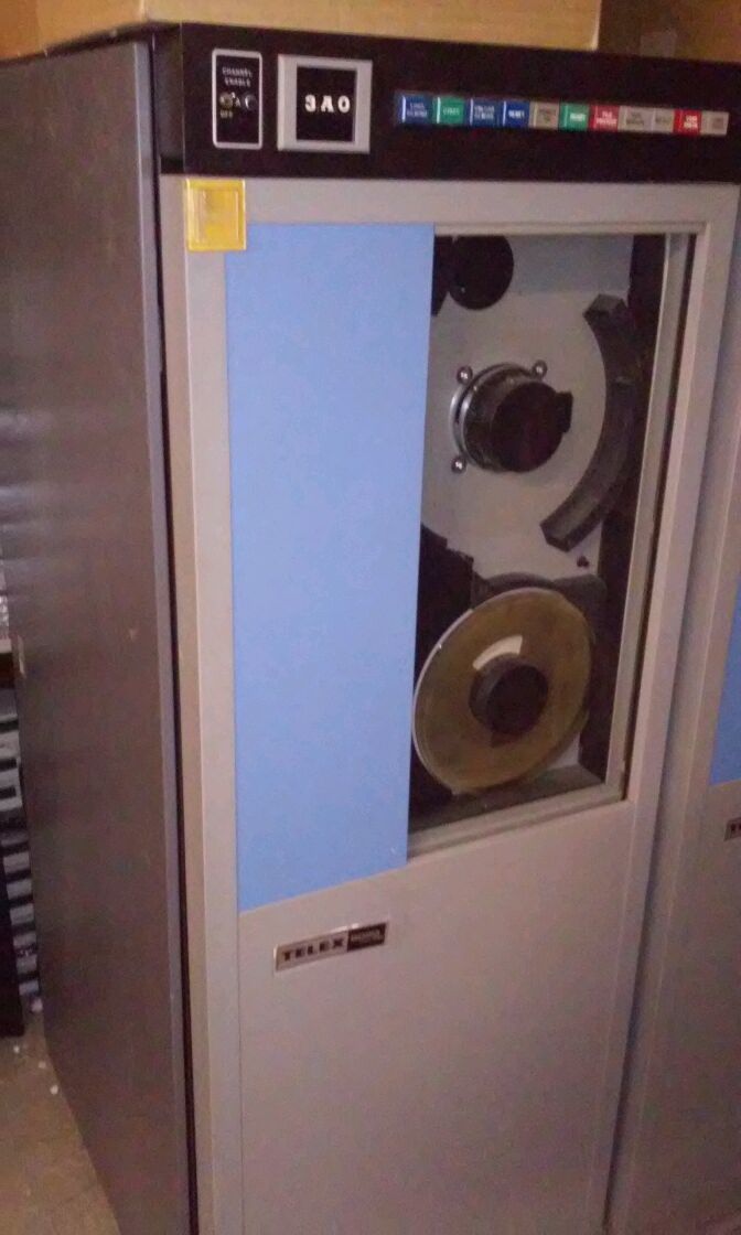 |
| One of the two tape drives I bought |
READING OLD CARD DECKS FOR UNIVERSITY OF MICHIGAN
A researcher at the University of Michigan contacted the Computer History Museum concerning some decks of cards that represent experiments done in 1970. They asked if the museum could help read the decks and provide files of the content, allowing researchers to include those results in new research projects.
The best way to read them was with my Documation card reader and the adapter designed by Brian Knittel that reads the cards into PC files. I moved my setup to CHM yesterday and began reading decks.
The files consist of six boxes each having several decks of cards, but initially one of the six boxes is missing. I opened box 2 and read all 9 decks. I emailed the files and some explanation to the UofM professor and grad students to be sure they are happy with the results. It took a bit more than a half hour to process a box, thus I can finish up the other boxes on Wednesday.
Each card deck has a header card which has MTS punched as visible characters (you can see the letters holding the card up, with each letter taking several card columns to express). It also has some other data on the card which may be identifying information such as the punch file ID when this was punched by the Michigan TimeSharing System (MTS). The following cards seem to be four-column numbers packed across each card.
 |
| Header card |
 |
| Data card |
Subscribe to:
Posts (Atom)