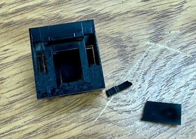
PROG LOAD SWITCH HAD A BROKEN SOCKET AND WAS WEDGED WITH PAPER
As I looked closer at the console when I was testing the Power on/off switch, I noticed some paper wedged into the side of the Prog Load button. The socket had been broken thus the button would pop up out of the socket when released. These sockets are a plastic piece that IBM used for both buttons and lights on all the SLT systems, with a single part that works for pushbuttons, toggle switches and lights.
The left side of the console has two dummy light positions that have a blank frosted white part inserted. Since they would not be used and are held in place by the metal console plate, I swapped a good socket from one of the dummy positions for the broken socket from the Prog Load button. The button is now as good as new.
POWER SWITCH CLEANED TO GET LOW RESISTANCE ON CONTACTS
I was not happy with the contact resistance of the Power On/Off toggle switch on the console. I had to remove it to clean it and get deoxidizing solution into the contacts. The switch is locked onto the plastic socket by a 9/16" hex nut but the gap between the switch body and the plastic socket didn't leave enough room for any tool to turn the nut. I even have some narrow IBM wrenches, but they were much too thick for the small space they needed to enter.
I went to the local Ace Hardware and while they don't carry any specialty very thin wrenches, they have cheap thin parts that come with grills, used by the staff when assembling grills for display. It was close enough to 9/16" and thin enough because of how cheaply it was made. It was perfect for loosening the hex nut and I soon had the switch out.
The switch was filthy inside the stem but I cleaned and deoxidized it, resulting in very good low resistance contacts in both positions. I reinstalled it into the console.
EPO (RED EMERGENCY SWITCH) HAD BEEN PULLED, RESET
In my debugging this morning I realized that the EPO switch had been pulled out by somebody years ago, in a childish desire to pull on the forbidden switch. The EPO switch locks into position when this happens, but it can be reset with a screwdriver from inside the display pedestal if you know how. It is now in its normal position and conducting electricity just fine. Somehow I had thought that I tested the EPO yesterday but obviously I did not.
TURNING ON THE POWER SWITCH ENERGIZED THE CONTACTOR
With the system circuit breaker turned on and a fuse in F5 to power the 24VAC transformer, the system was just waiting for the Power On/Off toggle to be moved to the On position. I heard a clunk and then a noisy contactor which delivered 230V to the majority of the fuses and other circuits inside the sequencer box. It also energized transformer T2 which will drop the 230V down to 115V to drive all the cooling blowers, but I disconnected T2 as I wasn't certain of the state of the blowers or what debris might be flung around if they came on.
VERY NOISY CONTACTOR, NEEDS RODENT DIRT REMOVED FROM CONTACTS
Loud buzzing in a contactor is a sign that the armatures are not pulled fully against the 'on' stop. This can be due to inadequate voltage on the solenoid but also by debris blocking the armatures from fully sealing. The latter is the much more likely scenario given the rodent nesting that took place inside the sequencer box. I will remove the contactor and clean it up so that it will work quietly.
RELAY R3 FOR CONVENIENCE OUTLET POWER FROZE UP AGAIN
The rust solidified again and is keeping the armature from moving on R3. This blocks application of 230V to the fuseholders F3 and F4 which feed the primary of transformer T3. That transformer drops the 230 to 115 and feeds power to the convenience outlets in the 1130 system and its peripherals.
The relay switches 230V to the transformer primary with the fuses specified at 3 2/10 amperes each to support loads of up to about 735 watts in total on the convenience outlets. If I get a replacement relay, its coil should work with 24VAC and its contacts have to handle the high voltage and 3.2A currents, plus tolerate reverse EMF when the power to the machine is turned off by the circuit breaker or pulling the plug from the building. It should also mount in the footprint and area where the existing R3 fits.
I won't spend the money on this relay until I am further along in the restoration and comfortable that it will be restored to full working order. At that point I can purchase a substitute relay and install it.


No comments:
Post a Comment