Sunday, February 4, 2024

Finished installing the missing paper feed parts and levers - part 5

INSTALLED REST OF MISSING PARTS ONTO 1053

Having secured an appropriate sized circlip from a donor machine, although used in a different spot in that machine, I completed the assembly of the main paper feed parts. Everything went together well and match my own 1053. 

The end of the release rod rides on a cammed lever control that the operator uses when inserting or repositioning paper. That was installed with the heavy duty circlips and works well. 


The last set of parts to connect were the control lever and related items that switch the index (line feed) function between single line spacing and double line spacing. That too was soon complete and I could now put the rollers, chromed plate and platen in place on the typewriter. 

I have some adjusting to complete in order to have the roller provide uniform contact across the page width and release well when needed. I began the process but will finish up on the next shop visit.


Saturday, February 3, 2024

Installing the missing paper feed parts and levers - part 4

BOUGHT SNAP-RING (CIRCLIP) PLIERS WITH SMALL DIAMETER PIN TO REMOVE PARTS

I measured the holes in the circlips IBM uses on the Selectric - they were 0.050" diameter. My existing pliers are either .58" or .76" diameter thus they won't fit into the hole of the ring/clip. 

I looked for pliers that had a small enough pin to fit into the clips and open them. I found a set at a local home improvement store that include 0.039" pins and purchased them. They worked well and I removed all the clips and remaining parts for the paper feed mechanism. 

INSTALLED MISSING PARTS ONTO 1053

The rubber feed roller shafts install into the missing parts and push up against the bottom of the platen to hold the paper in position. A lever on the right will rotate part of the missing parts to pull the rollers away from the paper path. This is used to install a new sheet of paper or to adjust its position. Another lever selects the single/dual line feed position for how far the platen turns on an index (line feed) operation.

I threaded all the parts on the release rod first, inserting it from the side through each part and then secured with its circlip. These turn with the rod, moving the spring loaded levers down and away from the platen. The levers and springs were added as well, some with their own circlips, which were very challenging to reinstall because of their small size and the position in the machine.


I spent several hours fighting to get parts threaded together - such as 79 and 80 from the diagram above - and trying to put on the circlips like 78 which was a moderate size and 63 which was tinier. Several times the parts fell into the machine, requiring substantial time looking inside to locate and retrieve them for the next try. 

The tiny circlips were my undoing for today. They fell into the machine as I tried to position them and force them on. My luck ran out when one of them fell into the machine but didn't fall through. No amount of tilting and shaking of the 1053 would cause that clip to drop out. I have no spares of that clip. 

I had to stop work and measure the groove that the clip fits into, so that I can buy a replacement at a hardware store when I head back to the shop tomorrow. I was trying to hard to complete the main feed assembly before I left but the missing part made that impossible. 

Friday, February 2, 2024

Installing the missing paper feed parts and levers - part 3

DONOR MACHINE PROCURED - SECOND TRY

I found a 13" paper width machine that had the tie rod paper feed mechanism. The seller struggled to pack it - reporting that it is in a banana box, with padded envelopes around it, the platen removed to allow it to fit in that box. The banana box is inside an outer box of some kind. No report of any additional padding between the two boxes. 

 I bought it to remove the parts that were missing from the 1053. It is unlikely, no matter how smashed up the unit gets during shipment, that the paper feed parts themselves will be damaged. The levers for paper release and single/double line spacing might, but I have spares from the other Selectric I bought. 

The moment of truth was when the package arrived on Friday. The outer box was undented and held its shape well. The typewriter inside was undamaged and ready to open up. 


Tie-rod paper feed mechanism - just what we need

REMOVING PARTS FROM DONOR MACHINE

I removed almost every part that is missing from the 1053 but there are a few spots where IBM uses some heavy duty outside circlips that require a strong tool to remove. All the circlip pliers I own have pins that are too large a diameter to fit into the circlip holes. These are also quite strong making it very difficult to pry off with screwdrivers as I can with ordinary circlips. 

I will either buy some pliers that will work for this or grind down the pins of one of my pliers so that they fit into the clip holes. I need to get this off to remove the last parts necessary to swap over to the 1053 and restore it to full operation. 

Monday, January 29, 2024

Replacement current column pointer installed

1053 COVER REQUIRES SPECIAL POINTERS DUE TO DEPTH OF ENCLOSURE

The cover of the Console Printer (1053) has the Selectric mechanism against the rear edge, leaving room in the front for the Console Entry Switches and other controls without interfering the the carrier and other typewriter parts. The extra room is only about two inches of depth, sufficient for the toggle switches and other additions. 

In an ordinary Selectric, such as office machines, the cover sits just in front of the typewriter mechanism so that the pointers for current position and margins are less than one inch long and still stick out of the front of the cover. The corresponding parts for the 1053 must extend out the extra two inches, thus the margin release levers and the column pointer are unique to this model.

The front panel of the 1053 has a plexiglass window running the width of the print line but a fraction of an inch high. There are column numbers and tick marks on this panel, allowing the operator to consistently set margins and space the carrier to a desired column of the print line. 

The tips of the margin levers and current column pointer are roughly triangular as they sit just behind the window, with the tip pointing at the tick mark where they are set. The margin indicators are blue and the current column pointer tip is metallic silver. The levers and pointer extend out from the margin rack and carrier and have the tip just behind the window at the appropriate height so they can be seen. 

SHEET METAL REPLACEMENT COBBLED TOGETHER

I measured the pointer from my working 1053 and fashioned a substitute from some sheet aluminum using tin snips and a drill, giving me a metal tip that would be visible in the window at the proper point. I mounted this and tweaked it until it was suitable. 

The pointer looks a bit rough up close, but all that is seen by an operator or museum visitor is the metal tip through the window. Just as the repair of the broken right margin lever is not visible except when opening covers or working on the machine, this pointer is similarly hidden. 


Thursday, January 25, 2024

Proper donor typewriter identified and bought - should arrive in a week or so

I found a Selectric 1 (original) 13" model on eBay. The seller included a photo of the broken rotate metal tape which occurred as he tried to lubricate the machine. In that picture I can see the ends of the paper feed mechanism (barely, with adjustment of exposure and contrast) and these look to be definitive for the tie-rod style paper feed mechanism. 

The shipping definitely adds to the cost, almost the same cost as the typewriter itself due to weight and size, but I didn't see any local Selectric 1 13" models that I could drive and pick up in any of the online marketplaces I tried. 


Wednesday, January 24, 2024

Installing the missing paper feed parts and levers - part 2

DONOR MACHINE PROCURED - FIRST TRY

I found a 13" paper width machine that had the tie rod paper feed mechanism. It was nearby, only $80 and while listed as a parts machine it appeared to only be suffering from solidified lubricants. I bought it to remove the parts that were missing from the 1053. 

I thought I had checked that it was a tie-rod style, but when I removed the cover, it had the useless A-frame mechanism. I tore it apart to harvest parts that I might need for other 1053 repairs. Time to look again to find the right kind of machine. 

The paper feed mechanism is hidden inside the cover of the typewriter, but some could be seen if the platen is removed, the chrome deflector has to be taken up as well and then I need a decently lit focused picture in order to verify the type of paper feed installed. Most listings for used Selectric typewriters consist of blurry or exterior only pictures. It can be hard to even see the paper centering scale that proves it is a 13" machine rather than an 11" or 8 1/2" model. 

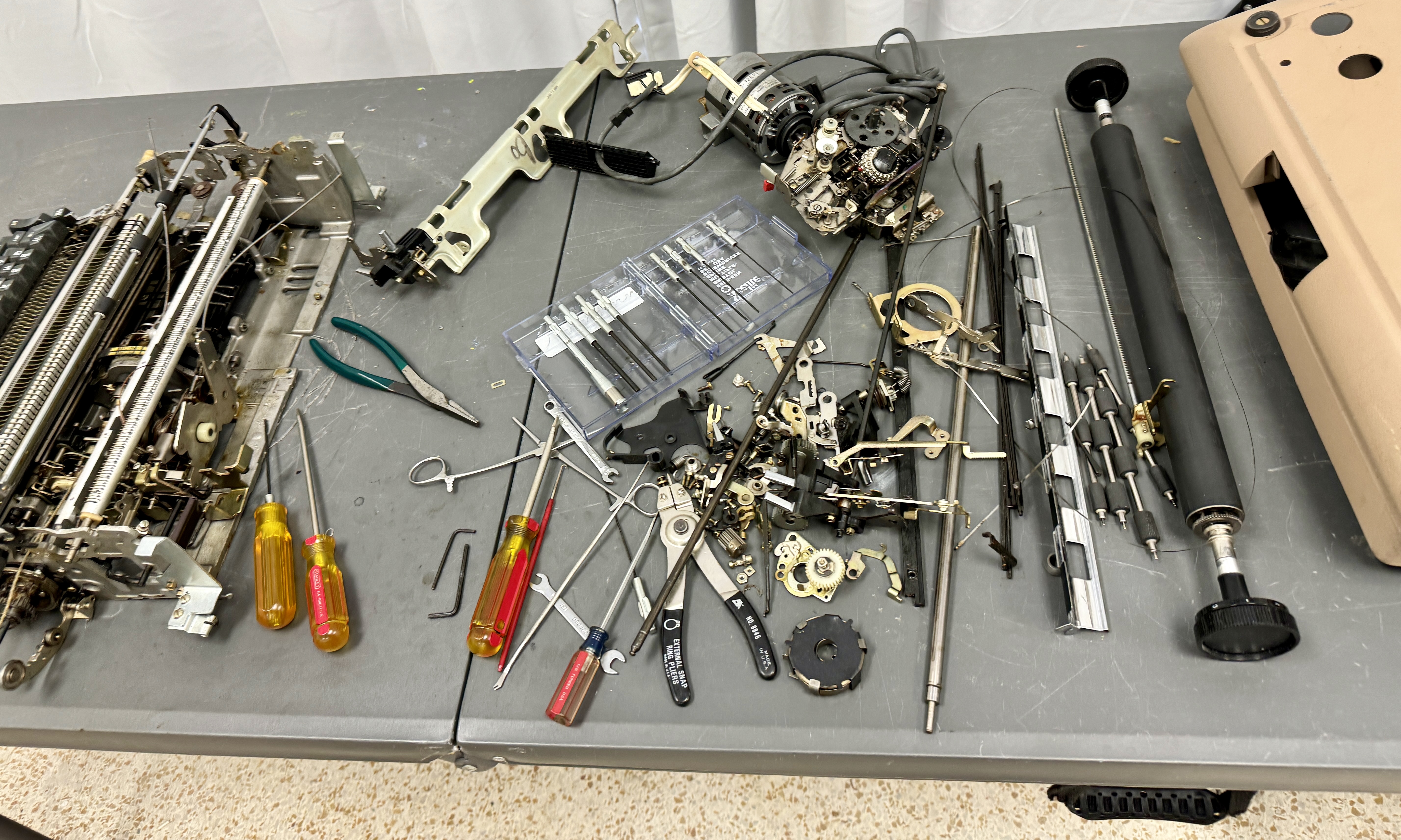
Process of stripping the new donor for parts


Tuesday, January 23, 2024

Installing the missing paper feed parts and levers - part 1

MORE ABOUT MISSING PARTS ON THE 1053

Here are pictures of the machine with its parts missing. 

left side

middle

right side

missing lever parts inside

missing lever parts outside

Next I show pictures of my own 1053 with the parts in place for comparison.


DONOR MACHINE POSSIBILITIES

The 1053 is a 13" machine - the size of the printable area from leftmost column to rightmost column. Further, it uses the tie-rod style paper feed mechanism. Very fortunately, not only did the 1053 not change this area at all from the office products typewriter versions, but IBM did not change the tie-rod mechanism at all between Selectric, Selectric II and Selectric III models. 

Pretty much any 13" machine with tie-rod feed is a suitable donor. This gives the largest possible pool of used machines that could be exploited to donate the missing parts.  I am confident I can find a machine within easy driving distance that I can verify as a tie-rod model before buying. I am feeling much more optimistic about the full restoration of this 1053. 

ANOTHER MISSING PART DETECTED - POSITION POINTER

The 1053 has a long metal rod attached to the front of the carrier whose tip is visible in the window of the printer front panel. It shows the current column where the carrier is sitting. On regular typewriters this is a short red pointer. 

Pointer on my good 1053 

missing pointer on 1053 being restored

I believe I can fashion a replacement from sheet metal since that is the material used on the original IBM part. Basically a matter of measuring, cutting out the shape, drilling two holes and then putting a few bends into it. It will be good as long as the tip is the right distance forward of the carrier, the proper height to be in line with the two margin lever tips, and the correct distance to the left of the mounting point to properly identify the carrier's current column position.