Sunday, March 3, 2024

Installing 1053 on the IBM 1130, with unforseen snags

 FINISHING INSTALLATION OF TYPEWRITER ON THE 1130

The cables were threaded down into the machine and plugged into the connectors down below the disk drive. I tidied this area up and reinstalled the covers on the disk drive while I was in this part of the machine. 

The front panel for the 1053 holds the 16 console entry switches, the three pushbuttons (Tab, Space and Return), the tab Set/Clear lever and a window through which the current column, left margin and right margin indicators can be viewed. I have enhanced this with a console loader device which will load memory as controlled by ASCII files sent over a USB cable - the device can be seen at the bottom of the front panel. 

Console loader at bottom

I located the rod that connects the tab set/clear mechanism on the typewriter side to the plastic Set/Clear lever on the front plate of the 1053. I put it in place and adjusted it so that it operated properly. I then lowered the cover down onto the 1053, making sure to connect the cable to the paper break microswitch near the top rear before locking the cover down in place.

I then put the feed rollers, deflector, and platen onto the typewriter. There is a round metal rod that the pin feed brackets on the side of the platen fit onto, which keeps them from rotating. I found this in the box of parts that came with the 1130 and put it into place. Loading a bit of paper made the 1053 ready for use.

Typewriter ready for paper

OXIDIZED FORMS CHECK MICROSWITCH

I had put paper in the printer but the Forms Check lamp was lit on the computer. There is a small roller that senses that there is paper entering the typewriter and stops programs from printing when the paper runs out. This system is designed to use continuous forms with pin feed, generally this lights when the box of forms becomes empty and it is time to swap in a new box. 
Roller visible above the metal bar

The roller pops up when there is no paper, but is held down by the paper to signal to the controller electronics that we have paper in the printer. In spite of the roller being down due to the paper, however, the machine registered this as empty. I pulled the cover off the machine and did some continuity testing.

Switch controlled by the roller

The switch contacts were so oxidized that the switch continually presented an open circuit. I deoxidized the microswitch and restored it to operation. When the roller is pressed down the computer is happy; when it pops up the Forms Check lamp goes on. 

POWER UP AND TESTED PUSHBUTTONS - RETURN DOESN'T WORK

When I pushed the TAB button, the carrier zoomed to the column with a tab set. When I hit the SPACE button, it spaced over one column per push. However, when I pushed the RETURN button it did not activate.

The pushbutton is spring loaded with a plunger that pushes on a lever. That lever is coupled by a flexible wire inside a sheath to another lever just above the operational triggers. I can see the two levers moving when I push the button, but it does not move enough to trip the CR trigger, unlike the other two buttons whose levers do reliably trip their clutches. 

Plunger of button pushes upward on the lever

Second lever attached by sheathed flexible wire

When I did the restoration of the 1053 on the workbench, it was without the front panel. I pushed on the first levers that the button plungers strike with each of them always activating their clutches. I therefore thought everything was dialed in and ready to go, but one thing is still not working, the pushbutton on the panel. 

I am trying to adjust this but it involves a cycle of lifting the 1053, removing the panel, adjusting something, and reassembling, with no easy way to know that it will work until it is all together. I also have to prop up the 1053 and attach the hand cycle tool in case it does trigger and I have to make the machine complete the return action 

I ended the day in the shop without yet having gotten a satisfactory adjustment for the RETURN pushbutton. I will focus on this when I return tomorrow, then when the button is working I can begin the checkout of the controller electronics and overall 1053 operation. 

Saturday, March 2, 2024

Loading new dual color ribbon in the cartridges

1053 HAS A DUAL PRINT COLOR FEATURE - RED AND BLACK

The 1053 is based on the original IBM Selectric typewriters which came in two versions, fabric and plastic ribbons. Selectrics also came in multiple platen widths, such as 11", 13" and 15". The model number reflects both of the choices, a 711 is a 11" width with mylar ribbon while the 725 is the 15" width and of course 715 is a mylar 15" model. 

The fabric ribbons fit in a small plastic case that snaps onto the top of the carrier. The standard typewriter Selectric has a lever on the carrier that chooses which part of the ribbon is used for typing. Once setting, stencil, does not lift the ribbon between type ball and paper. The other three settings determine whether the top third, middle, or bottom third of the ribbon is where the ball strikes. 

Typists could install a dual color ribbon cartridge and then manually select the top third or bottom third to pick which color they wanted for their typed characters. The 1053 added a mechanism with a ribbon color tape running to the carrier similarly to how the tilt and rotate tapes connect. 

Depending on the tension on the ribbon color tape, the carrier is either selecting the top third or the bottom third of the ribbon. A set of solenoids on the left lower side of the 1053 select between two tensions on the ribbon color tape. 

VERY HARD TO FIND THE DUAL COLOR FABRIC RIBBONS FOR SELECTRIC 72

I have not seen any new old stock in a while, although I own two of those cartridges. The ink is fairly dry so the print quality is not very good and will only get worse with age. There is a manufacturer in Germany producing replacement fabric ribbon for the Selectric 72 but each cartridge is quite expensive; the international shipping drives the total up to roughly $100 each. 

BOUGHT SOME NEWLY MADE DUAL COLOR FABRIC RIBBONS 

I found a supplier of new black/red ribbons on open round spools as used on many older typewriters. I will open the cartridges, remove the stale ribbon and reload it with the new ribbon to produce new stock for the 1130 systems. I saw a YouTube video where Duane Jensen (of the Phoenix Typewriter channel) reloaded a cartridge with fresh ribbon. In his case it was the monocolor black ribbon but the principal will be the same. 

Motor power test of the 1053 functionality - everything works properly

USING MY SMS CONNECTOR SYSTEM TO HOOK TO THE 1053 CABLES

I developed a PCB that I can use to make SMS connectors, both the male 'paddle cards' and the female sockets, since the typewriter has one of each type that plug into the IBM 1130. This is on github under my account in case others want to use them.

When used as a socket, the flat conductor 'fingers' of the socket and the flat conductor fingers of the 1053 paddle card don't make good contact across all thirteen fingers due to flexing of the PCBs. To solve this, I bought some surface mount RF finger components - little parts that solder onto the fingers and have a springy top to ensure contact. After soldering these on a socket PCB I had perfect connectivity between the 1053 male paddle card and my socket. 


These are wired into the relay system I set up to trigger the 1053 solenoids with appropriate duration to activate all the functions of the typewriter that are controlled by the mainframe. The breadboard unit has a timer circuit to produce the correct length pulse which turns on the +48V, energizing every solenoid that is grounded by a relay on the large relay board. 

CHECKING PRINT CHARACTERS

I first set up a set of characters to verify that I could select the eleven rotate positions from -5 to +5 as well as the four tilt levels properly. It was enough to have one character from each tilt level and one from each of the eleven rotates; I could overlap the test so that four characters tested the tilt plus four of the eleven rotates, then another seven characters would fill out the rotate completement. 

Then I had to do another eleven characters to test the rotate positions on the other side after shifting the ball from upper to lower case. Only when all 22 characters and the shifts were verified was I satisfied that character printing was correct. 

Visually I inspected the output to refine the vertical position of the platen, so that a character is evenly inked top and bottom. I also inspected to verify that the carrier movement at the end of the print cycle does not produce any smearing and that letters are evenly spaced across the line. 

Perfect!

VERIFYING THE UP SHIFT AND DOWN SHIFT OPERATIONS

The up shift and down shift solenoids won't activate with the very brief pulse used to print characters or trigger the other operations, but a slightly longer activation causes a crisp shift to the requested case. Again, works fine. 

VERIFYING DUAL COLOR PRINTING

After tweaking the tension, I could command printing from the top or bottom half of the ribbon, thus printing in black or red ink. 

VERIFYING SPACE BUTTON AND SOLENOID

When I push the Space button on the front of the typewriter, it cleanly moves one column to the right for each push. Activating the space solenoid does the same and I could fire off a string of rapid spaces which moved the carrier cleanly. 

VERIFYING BACKSPACE

My test setup sent backspace solenoid commands to the typewriter and I verified it moved precisely one column back on each iteration.

VERIFYING TAB BUTTON AND SOLENOID

Pushing the Tab button on the front of the typewriter causes the carrier to zoom to the right and stop at the column where a tab is in the set position. Firing the tab solenoid does the same. 

VERIFYING CARRIER RETURN BUTTON AND SOLENOID

Pushing the Return button on the front of the 1053 causes the carrier to race leftwards and stop exactly at the left margin, ready to resume printing at that column. The carrier return solenoid does this as well. The return function also triggers an Index operation, thus we move down a line and return to the left margin in the same operation. 

VERIFYING INDEX

Activating the index solenoid rotates the platen to move the paper up one line position at a time. 

VERIFYING MARGIN LEVERS WORK PROPERLY

Moving the left and right margin levers, I verified that they move smoothly and latch into the chosen column when released. The return stops at the left margin, the bell rings when you approach the right margin and everything is as it should be. 

VERIFYING GANG CLEAR OF TAB SETTINGS

When the tab lever is rotated on the front of the typewriter, it will either set or clear the tab at the current column. A convenient feature of Selectric typewriters is gang clearing. This means that with the carrier at the right margin, if you hold the tab lever in the clear position and hit return, the machine clears all the tabs between the starting point and the left margin where the carrier stops. This worked properly. 

CONDITION ASSESSMENT

Having passed all the tests above, the 1053 is now able to perform everything it needs to do before the 1053 is reinstalled onto the IBM 1130. 

INSTALLATION ON THE MACHINE

I connected the front panel to the typewriter and placed the unit under the display pedestal. I ran out of time to finish the installation but will perform this tomorrow when I get back to the shop. 

I have to do the following:

  • install the rod that connects the front panel tab Clear/Set lever
  • reconnect the forms out microswitch on the cover to the typewriter
  • put the cover on and snap it into place
  • insert the paper feed rollers and related parts
  • put on the rod which holds the pin feed arms in place
  • install the platen with its pin feed arms
  • route the cables down through the 1130 to under the disk drive
  • plug in the two signal cables to the SMS peripheral connector bank
  • plug in the SMS power paddle connector to the power bank

Adjusting the rotate character selection on the 1053 - success!

TO ME THE MOST IMPORTANT ADJUSTMENT IS DETENT TIMING

In a print cycle, the whiffle tree applies tension (or relaxes tension for negative rotations) to the tilt and rotate system which turns and tilts the ball. The detent should be locking in those movements once they are complete. However, I have noticed that if the detent moves in while the rotate lever arm is still in motion because the cams are still pushing down on the selection bail, then the ball can be stopped before it rotates to its final position. 

bottom shows jammed tilt


Thus, once I have the tilt and rotate levers moving properly and the ball tilting and turning to the correct rough position, I just have to tweak the timing of the print shaft so that it does NOT activate the detents until the selection movement is complete. 

RESULT OF ROTATE SELECTION OF CHARACTERS

I finished up the adjustments today and tried a number of different characters to test out the tilt and rotate behavior when hand-cycled. The  check is a verification that all is now set up properly. It consists of selecting four characters and comparing where the detent occurs - it must be 'within .0015" of each other in the negative direction.' The characters are chosen to have a -5, a +5, a 0 and a -1 rotate. If this test is failed, we would have needed to iterate through the tests and adjustments until this works. 

Everything locked in perfectly and detented at the correct place. 

SHIFT MOTION ADJUSTMENT

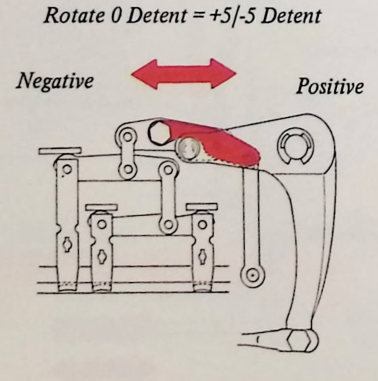
The shift pivot arm on the right side of the typewriter adds enough pull to the tape to rotate the ball 180 degrees exactly to the 'upper case' hemisphere or relax it to go back to 'lower case'. The test is that the detent enters the tooth for a UC and LC -5 character at exactly the same point and it withdraws at exactly the same time in the cycle. If the UC is not the same, an adjustable stop screw is turned until we pass the test. 

completely false diagram, the adjuster does not look like this

The adjustment, like most on this bedeviled typewriter, was quite a bit off. The typewriter was selecting characters from the upper case side of the ball perfectly, but would miss the +5 column on the lower case side. There is a nut-head screw that determines the tension of the lower case position and it had to be adjusted. 

Access was difficult, so I had to remove a couple of parts and fight because both the nut-head and the locking nut beneath it are thin - thinner than most wrenches which makes it difficult to hold one and turn the other. 

Hex head bolt just under the black rod is the adjustment

The bolt head is very thin and the lock nut is just behind it

I was able to get it adjusted properly and then iterated back to test the selection in both upper and lower case. After another pass adjusting the print shaft timing, the machine was selecting very reliably. 

FINAL CHECK

I also checked selection under motor power. First I stopped the ball with the Dynamic Half Cycle Tool when it had locked the ball in place, allowing me to visually confirm the character. Later I let a few characters type through a ribbon onto paper on the platen which is the ultimate test. 

PLATEN ADJUSTMENTS

What was typed on the paper was inspected to insure that the top and bottoms of the letter were equally dark. The solution if not is to move the platen up or down with side adjustments until the print is perfect. Fortunately this was good as it stands. 

RIBBON COLOR SHIFT ADJUSTED

I tweaked the tension of the ribbon color string so that the type comes out in red or black as we activate the Shift to Red and Shift to Black solenoids. This requires the special dual color ribbon, which can be acquired various ways. 
Type changed from black to red with solenoid activation

A ribbon manufacturer makes new versions of this in Germany, but between the cost of the ribbon and the cost of shipping, a single ribbon is about $100 delivered here. From time to time you can find new-old stock ribbons and so far every one I have tried was not dried out. Finally, there are suppliers of the right width of dual color ribbon, thus presumably you can buy this, open the stale cartridge and put in the new ribbon. 

Friday, March 1, 2024

Adjusting the rotate character selection on the 1053 - final round part 3

BALANCE ARM ISSUE AND CORRECTION

The parts didn't slide far enough when I tried to use the screwdriver on the slots on the top of the arm, but by pushing the two sides I was able to get the two versions of zero rotate to match. 


REDOING OTHER ADJUSTMENT STEPS

I retimed the print shaft and tweaked the lever point of the rotate arm as shown below.


What I discovered is that the amount of rotation is enough to reach all eleven positions, from +5 through to -5, but the detent which locks the ball in place was not working reliably. Part of that is a timing adjustment I have to tweak, as currently the detent stops the ball while the machine is still moving the rotate tape to its final position. This can lock the ball into the wrong column.


NAIVELY ASSUMED THE TILT ADJUSTMENTS WERE CORRECT

I had been assuming all along that the tilt selection was correct. First, the machine came with the rotate tape broken but the tilt tape was intact thus presumably set up properly. Second, I could see that the machine moved the ball to four distinct tilt positions as I selected characters during my time working on rotate, so I just assumed it was doing it correctly.

I had been working on a flaky detent during rotation, where sometimes the rotation detent didn't enter the tooth fully and would snap in place when I lightly rocked the ball. I had been inspecting for burrs and lubricating it when I realized that in fact this was caused by a tilt misadjustment, 

The detent system first locks in the tilt and then continues on to lock in rotation. Tilt is simple, just four teeth inside on a pivoting arm, but if the tilt arm doesn't fall into a tooth then the rotation detent can't pull up into the ball teeth. 

I found that the selection was falling right at the high point between teeth, so that sometimes the tilt locked in properly but other times it hung up on the high point. The ball seemed to be tilted but it was in between the rows. 

The adjustment was super easy and now the tilt locks in properly, thus the detent for rotation is reliable. 

GOING BACK TOMORROW TO READJUST ROTATION 

I am feeling confident that I will get this 1053 dialed in with proper character selection. It is just a matter of iterating through the settings. In spite of step by step procedures published by IBM, which imply that these don't interact with each other, I have found that I have to repeat adjustments or loop through sets of adjustments if I want to get things working as they should. 

Thursday, February 29, 2024

Adjusting the rotate character selection on the 1053 - final round part 2

CAREFUL ADJUSTMENT OF EVERY ITEM IN THE PROCEDURES

I prop up the front of the typewriter to have access to the selection magnets underneath which are used to trigger printing a character. Often I have to stop the hand cycling at a point such as when the detent begins to lock down the ball position or when the check pawl drops into place at the end or middle of a print cycle. This involves rotating the typewriter to see those areas.

Propped up 1053 allowing access to underneath

Selection magnet bars 

Setting the initial home position requires that the setscrew be loosened on the underside of the shaft that rotates the typeball. One has to put the typewriter on its back with the carrier all the way on the left and then use a very long bristol wrench driver to loosen and tighten the setscrew. 

Top of typewriter on left, wrench used on setscrew

Turning ball while setscrew is loose

ROTATE ARM POSITION AND PIVOT

The resting position of the rotate arm lever is the position where the typeball will sit for the 0 rotation column, called the home column. Further, its pivot point determines how much the ball twists as the lever arm tilts a particular amount based on the R1/R2/R2A/R5 selection levers. We adjust to get good selection of both negative 5 and positive 5 columns. 


BALANCE ARM MUST BALANCE NEGATIVE AND POSITIVE ROTATION AMOUNTS

The R5 lever pivots a lever that works in the opposite direction to the other selection levers (R1, R2A and R2). This lever is activated when its selection magnet is energized. The other rotate levers are activated when their magnet is NOT energized; the magnet operation causes the lever to be removed from the bail so it does not move down.

If only the R5 lever is activated, with the other three magnets energized so that the levers are NOT active, the ball rotates to the -5 position. If R1, R2 or R2A levers are activated because the selection magnet is off, it pulls down with the bail and offsets some of the negative movement of R5. In a sense it is signed addition, where the R1 lever moving down at the same time as R5 will add a +1 and the -5 to select a rotation position of -4. 

To ensure that the amount of position and negative movement is the same, the balance arm must be adjusted. This is accomplished by comparing the position of the ball when no levers are pulled down (R1, R2A and R2 energized, R5 not), to an alternative called IO Home. 

In the first case, no levers are pulled down the the bail so the ball does not turn at all. In the second case, we do not energize R1, R2A or R2 but energize R5. The first three develop a +5 movement and the R5 adds a -5 movement, thus arithmetically zero. 

If the ball is in the same position in both cases, then we know that the +5 motion of R1, R2A and R2 are exactly balanced by R5. The parts of the balance arm are slid together or apart to achieve the balance we want. 

Balance arm with R5 on right and the other levers on left

I was NOT able to get the balance arm to completely zero out the differences between the two types of zero. I adjusted it as close as it could get but ultimately the rotation of the ball is not correct because of this. 

TYPEBALL FINAL ALIGNMENT

The type ball home position is adjusted again by lengthening or shortening the pushrod that couples the whiffle tree selection mechanism to the rotate arm, moving it in or outward. This must be done to ensure that the detent teeth are entering at the right point in the triangle. This assures the most reliable character selection in spite of minor variations in the amount of tilt and rotation in a particular print cycle. 

PRINT SHAFT FINAL ALIGNMENT

The print shaft is rotated relative to the print cycle shaft to cause the detent and striking operations of the carrier to happen at the best possible time in the print cycle. One gear is loosened and the shaft is turned by hand to reach that point, while observing the operation of detent teeth. This is the ultimate adjustment for character selection. If done correctly the typewriter should reliably select the correct character from among all 44 on a side every time it prints. 


Gear on top is loosened to adjust print shaft timing

RESULTS NOT SATISFACTORY

In spite of being very careful and thorough in going through the settings, without having the balance lever set correctly it was not possible to have the ball rotate reliably to both +5 and -5 positions. These were the symptoms I started with before I began the adjustments. 

I tried to adjust other areas to compensate but I am fairly convinced that the balance arm disparity is the smoking gun that is either the cause or indicating the root cause of the issues. I will have to study the parts from the donor typewriter, compare positions and appearances closely between the working this 1053, and get this resolved during my next session at the shop. 

Wednesday, February 28, 2024

Adjusting the rotate character selection on the 1053 - final part 1

 INITIAL ALIGNMENT ADJUSTMENTS

The print shaft has to be rotated so the groove is in a particular location so that the movements of the ball and related parts in the carrier are at an appropriate time compared to when the tilt and rotate tapes are being moved. This is a very easy visual adjustment. The position of the shaft is refined near the end to fine tune the print operation. 


The initial position of the typeball relative to the detent teeth has to be established by loosening a setscrew from underneath and then twisting the ball in a specific procedure. The detent teeth move into the triangle openings around the bottom perimeter of the type ball to lock it to a specific location just before the ball strikes the paper. The tilt and rotate mechanisms only need to move the ball close enough so the detent enters the proper triangle opening. 


BALANCE ARM ADJUSTMENT

Since the typeball has to rotate nearly 180 degrees to reach all eleven columns of characters, the rotate mechanism twists the ball in both directions with five possible amounts of twist per direction. This is accomplished by the R1, R2 and R2A levers which move the rotate arm from zero to five units of movement. The R5 lever moves the balance lever, which provides five units of movement in the opposite direction. 

Thus, R5 with no other levers will move five units in the negative direction, R5 with just the R1 lever moves four units in the negative direction, R1 with no other levers moves one unit in the positive direction and so forth. We need to adjust the balance arm so that its operation is exactly equal to the movement of five units from the R1/R2/R2A levers. 


When I checked this, the position of the ball with latched home versus I/O home was quite different. When I am in the shop again tomorrow I will adjust the balance arm to equal this out and then proceed with the following adjustment steps.