The drive belt gave up the ghost, splitting when I applied motor power. Someone has put two belts on the main shaft, turned inside out and tied into a small bundle, so they just hang on the shaft while it turns. this allows someone (me) to untie the bundle and move the belt over to its pulley without having to remove the shaft or disrupt any settings. Quite a nice idea and a real timesaver. The replacement belt seems in much better shape - I am hoping it will work okay in spite of its age.
 |
| Broken drive belt from typewriter mechanism |
 |
| Cogged pulley where the belt should be attached in center |
 |
| Spare belts, inside out and tied in bundle to hang on main shaft |
 |
| One of the spare belts being moved over to the pulley for installation |
 |
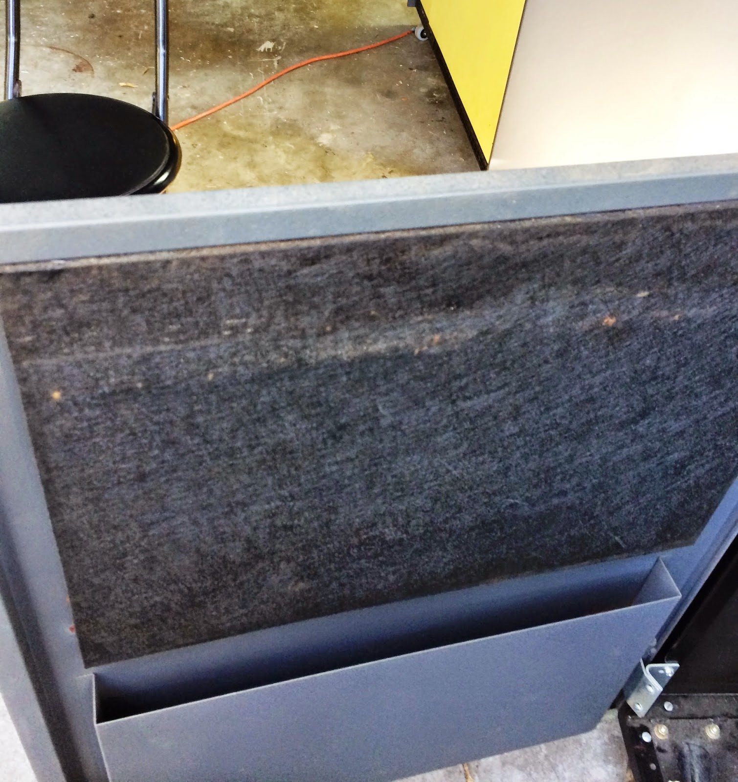
| Typewriter cover with new sound deadening liner inside |
I did a bit of reseating of cards and cables, and the memory seemed to be working much better. I will do some more comprehensive testing when I next power the machine up but I am encouraged.
PANEL LAMPS
I found some lamps that are similar, type T2 but a slightly higher voltage, and replaced bulbs that weren't working. I continued to experience bulbs failing (wires separating at their entry point into the glass) from the slightest touch. Since each row of lights has to be worked into position in the plastic grid, it is not possible to avoid brushing against the bulb.
I need a source for 150 lamps of the right type, either the original 4.5V or 6V alternatives, as the difference in apparent brightness is not very noticeable. I placed an order for 40, which was the limit of the on-hand stock, to check out a particular brand and supply.
The process of swinging a board of 16 lights out of the plastic grid, replacing the bulbs and then re-positioning the board into the grid holes is quite fiddly and inexact. Even when I have new bulbs that won't snap their leads at the slightest provocation, it will still be like herding cats when I try to get six boards all fitting into the grid at the same time.
1132 PRINTER RESTORATION STEPS
My first step was to undertake a goo hunt. Fortunately, the 1132 used the cloth sealed fiberglass method of sound deadening, which is holding up well. However, inside the SLT card compartment was the awful stuff I have encountered so much with this system. I scraped it out, cleaned the compartment cover, then installed a sponge neoprene lining where the goo had been.
 |
| Cloth sealed fiberglass sound deadening material |
 |
| Material and adhesive for neoprene installation |
 |
| SLT card compartment cover, goo removed but neoprene not yet added |
The printer had a filter for the air blower, which I updated with the new pleated filter material. There are signs of solidified grease and oil in the print mechanism. For example, the platen clutch had to be exercised a bit before it would turn all the way to disengage and back to engage.
I reformed the large electrolytic capacitors in the power supply. The 1132 gets the SLT logic voltages over the power cable from the 1131, but has its own power supply to generate 48V to power the print hammers. As with the other boxes, I had to rewrite it for 230V, but temporarily rewire it for 115V in order to use the Variac for reforming.
 |
| Variac set up to reform capacitors |
The 1132, like the 1442, gets its power delivered by cables from the 1131 system. The printer has a power sequencer with contactors to pass on the voltage only when the sequencing voltage arrives from the processor. The 1130 system generates 24VAC very early in power-up and sends that around to control the powerup of everything else. At the time that the 1131 sends sequencing power to the peripherals, that power activates the contactors to power the device.
In the 1132 printer, IBM designed a mechanism to discharge the electrolytic capacitors very rapidly once power is dropped. They do this via a contactor, energized by the 24VAC sequencing power and closing a circuit shorting the capacitors with a 10ohm, 10W wirewound resistor when the coil shuts off. The capacitors sit at 48V - this resistor has an initial discharge rate of 5 amperes and is handling over 200W at the outset, but both current and power drop quickly as the voltage is discharged.
If you sneak around the 24VAC and contactors, directly applying mains power to the power supply, the 10ohm resistor is a load across the output. By the time I got up to 48V on the caps, It was handling more than 20x its design power capacity, but valiantly converting that power into thermal and optical energy.
I can imagine the field problems whenever the contactor for the 10ohm discharge resistor would fail to energize - the same 250W would make that resistor glow and smoke. It is hidden under a metal cover inside the printer at the bottom, but the stench would alarm the operators. Might even cause a rapid power down of the system. I find the design odd.
I have a replacement I will pick up tomorrow for the overstressed resistor, since I want to get the 1132 under power and connected to the system next. After hauling the signal and power cables around, I tried to hook this up. The signal cable went in nicely, but the power cable wouldn't tighten into place. There is a knurled screw head on the back that pulls the connector into the socket firmly, but I couldn't feel the threads engaging at all.
Upon firther investigation, I saw that the thread end was not sticking out of the connector. Immediately, I realized I now knew the purpose of a strange part I found a week ago and put aside - it looked like a bolt thread connected to a basketball inflation needle. I will open the connector and then reassemble the tightener tomorrow, after which I can finish hooking up the 1132 for its first operational tests.
 |
| Power connector for 1132 printer, screw head removed from top |
 |
| Screw head in connector upper right, strange part I found lower left - a match! |
No comments:
Post a Comment