I reassembled the button/light control panel on the card reader and began to examine the mechanical state of the device. I discovered that two steel rollers under the rubber drive wheels that pull cards forward into the stackers were frozen with sludge inside the bearings. I added oil and loosened them up.
Still more to go before this reliably pulls cards to the stacker but it is almost working right. If I loosen or lift the plastic cover over the station where cards turn into the stacker, the cards are taken. That means that I have a bit of resistance to movement or a too little pull to make the cards move.
I turned to the check condition as the cards enter the read station and found that another of the metal rollers was frozen. This one is the read pressure arm roller which holds the card against a rough edged wheel that drags the card through the read station. The roller is very rough when it turns, sounding like a bearing is damaged inside the little wheel. The wheel is not designed to remove from the arm, instead the entire arm is the replacement part.
I won't find the spare part and will have to repair this arm myself. I will check with the TNMoC museum in the UK, who have a working 1442, to have them verify the read pressure roller should be smoothly rotating. A replacement roller with bearing will have to be located using a supplier like Grainger, the bad one removed and the new roller fasted on. This may require drilling off the end and implementing a new fastener on the end of the axle.
INTERNAL DISK DRIVE RESTORATION
Today I dropped the heads onto the rotating disk surface. They flew well, no scratches or interference at all. With the interface cable disconnected, I was able to move the arm in and out using the CE switches on the back of the drive. However, the drive won't load the heads automatically nor does it switch to file ready status when the cable is reconnected.
The solenoid has hold current continuously while the spindle motor is under power, but the pick current is needed to pull the solenoid slug in, after which the hold current is enough to retain it inside the coil against the pull of a return spring. When hold current drops,the arms leap up away from the disk platter surface due to the return spring.
The pick current is driven from a logic card when a set of conditions are all true:
- Expiration of a timer that waits 90 seconds from initial motor start to let the disk stabilize
- The carriage is at the home position (cylinder 0)
- The spindle is rotating no slower than 70% of target speed of 1500 RPM
- Heads are not already loaded onto the disk surface
KEYPUNCH INTERFACE DESIGN
I received my relay boards and Arduino, as well as the DB25 cable. Looking at the relay boards and the logic gate of the keypunch, I immediately saw that the boards could be mounted on the gate, with short and appropriately thick wires. The wires inside most DB-25 cables is intended for low current signals and is marginal for driving punch solenoids.
 |
| Relay module, one of two used in the keypunch interface |
 |
| Almost perfect fit for relay over these openings, with standoffs through holes |
KEYBOARD TESTING
The keyboard on the 1131 processor is an 029 keypunch keyboard with a very simple interface. An IO instruction is issued to select the keyboard, which turns on the Select lamp to the left of the keyboard and waits for the user to enter keystrokes. The keyboard responded to the command, select turned on, it turns off when you do a read command, however the area where I requested the data was always zeroes. Further, pressing the interrupt request key should raise an interrupt condition, but it did not.
I have some debugging ahead for the keyboard and control logic circuits. Another case where I will use the scope to see what is occurring including any missing signals.
DISPLAY PANEL LAMP REPLACEMENTS
I opened up the display panel, with new bulbs in hand, and went through the slow tedious work of replacing bad bulbs and securing the lamps firmly in the separator grid behind the front panel. The new bulbs are very cheaply made, but at least they work properly when installed.
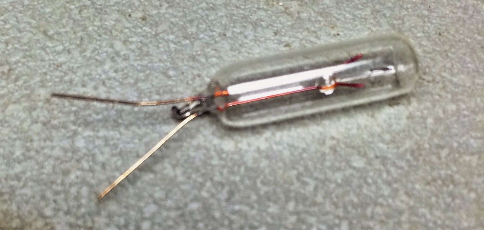 |
| Latest batch of lamps are low quality manufacturing |
I then worked on the last two rows, the A (Accumulator) and X (extention) registers. Alas, when I turned it on, there were a few dark spots and they were spread across multiple of the registers.
I took the front panel off the plastic grid, although that didn't really help in particular way. I worked for two solid hours trying to get the left side (six major register) all lit up and have them wedge in solidly into the plastic grid. It didn't work. For two of the bulb sites, I couldn't get the bulb to work. One of them appears to have a dead SCR driving the lamp, probably shorted out sometime in the past. The other was less conclusive but likely that is the problem,
 |
| Front panel removed |
 |
| Back of the front panel, where it is secured to the plastic grid |
 |
| Plastic grid into which the panel installs - lamps barely visible |
I threw in the towel for the night at 10PM, with five bits still dark. While three of them could simply be loose connections or dead bulbs, they could also be bad SCRs. The lower three register strips are very loose, so that touching one of them tends to dislodge the other two strips so they slide back away from their assigned openings.
Peter Vaughan of The National Museum of Computing in the UK sent me a very detailed report on the restoration of their 1442 reader/punch. Reassuring how the issues are so similar and their 1442 is working well after the restoration.
ReplyDelete