FINISHED SETTING UP THE TESTING RIG
I soldered and assembled the last 11 banana to breadboard jumpers, then wired up everything for testing this card. That involved several signals which are paired opposites (e.g. +T7 and -T7) so that one switch would flip both through the use of a buffer and inverter pair.
I discovered that the mode switch and pushbuttons have an odd circuit that does NOT use SLT logic levels. The switches are connected to +12V, through a 470 ohm resistor to the logic card. On the card, the 'Z-INT' gate has a 470 ohm resistor to ground and a capacitor whose far end is hooked to -3V. The junction where the signal arrives also has a 1.2K resistor bringing the signal to the SLT logic gate that will be driven by it.
The two 470 ohm resistors form a voltage divider giving +6V at the junction when the switch is connected to +12V. When not connected it is pulled down to ground. The SLT logic gate doesn't really care what the high voltage is, within limits, but provides a current flow down to any voltage lower than 3V such as the ground state of an un-activated switch signal.

I had to pull out another power supply and feed 12V through 470 ohm resistors to the two signals that connect to Z-INT gates on the card - the +Single Step Mode and the -Reset Key signals in this case. With it wired this way, the cards responded properly to the state of these two buttons.
I used the 100KHz oscillator of my CADET breadboard machine to drive the card and had nine switches and eight display LEDs set up. Additional circuits were monitored on my oscilloscope.
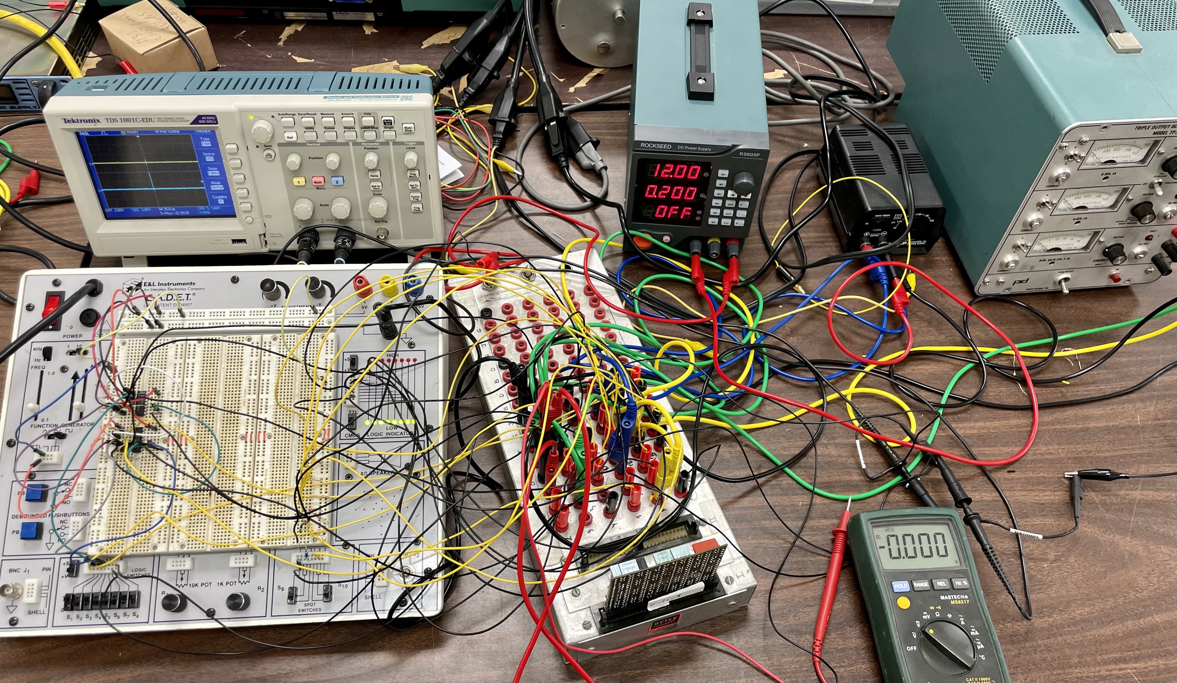 |
| Test setup |
INITIAL TESTS OF CARD 1 (FROM THE MACHINE)
I had a methodical set of test steps, beginning with testing the proper generation of system reset (DC Reset signal) both from the Power On Reset signal and the Reset Button activation. My second set of tests were to put the card in Single Step Mode and verify the proper state outputs include Phase A and Phase B clock signals.
I quickly determined that this card is not responding to the Program Start Key signals at all. I verified that the matched pair of opposite inputs are produced as I activate on of the logic switches on the breadboard, but the card doesn't respond at all. Since it doesn't respond in several modes, which involves different sets of logic gates, the defect must be early in the chain.
I couldn't test any further without the ability to put this in various modes and trigger the Run state.
INITIAL TESTS OF CARD 2 (FROM THEIR SPARE CARD COLLECTION)
This card behaved better in that it did respond to reset conditions and to the Program Start Key signals. I put it through its paces and found it well behaved in Single Step Mode. I seemed to work okay in Single Instruction Mode, where the signal -T7 Count 0 going off triggers the Run flipflop to turn off.
However, when I tried to step it in Single Storage Cycle mode, which resets when T7 is reached, provision of the proper T7 signals did not reset the flipflop.
Another path that requires T7 is recognition of the CPU Stop Latch. That is only checked at T7 time, as otherwise you would not complete the writeback of a memory word contents. The machine never responded to the CPU Stop Latch either which again points to failure of the T7 detection.
I felt that I could do some limited debugging with this card in the machine as long as I had it in either Single Step or Single Instruction modes. However, when I powered up the machine, I found that the lights on the keyboard did not illuminate (such as the Run state) and the machine was frozen.
A bit of debugging with the scope showed me that the Reset button signal was low, when it should be powered by +12V when inactive. I found that the 12V supply was not present anywhere in the machine.
NO 12V TO POWER BUTTON AND MODE SWITCH SIGNALS
My first investigation was to remove the small fuseholder on the power supply that protects the 12V generating transformer. The fuse came out and was good, but I couldn't get it back into the holder. The holder inner contact was twisted and bent in a way that blocked fuse insertion. I pulled the power supply again in order to replace the fuseholder.

TRIED TO PROVIDE 12V WITH A BENCH SUPPLY, BUT IT DIDN'T REACH LIGHTS
My bench supply can deliver the 4A of 12V that is the capacity of the supply with the broken fuseholder. I applied power but there was no draw at all on the supply. The machine has a relay that only connects the 12V and 48V once the other power supply levels are verified by the SMS power sensing card. Something must be wrong with this - investigating tomorrow.
No comments:
Post a Comment