BECOMING METHODICAL ABOUT NUMBERING THE RC MODULES FOR DOCUMENTATION
I came up with a naming scheme for the 30 non-SLT module components on the board, using C1 to C8 for the discrete capacitors and P1 to P22 for the other 2 to 6 pin components. I named the various modules and kept track of both the part number (e.g. 2390302) and the location of pin 1 for that module, since some are installed in the reverse sense to the others.
As I learn about the components inside, their values and the wiring, I am writing it down as it makes the process of reverse engineering the board easier. So far I understand five of the ten part numbers; the goal being to document all of them in order to fully understand the circuit and find any defects.
INTERESTING OBSERVATION ABOUT IMPLEMENTATION ALTERNATIVES
The logic for resetting the Run flipflop is a set of conditions determined by edge triggered AND gates, all fed together with the DC Reset signal into an OR gate which in turn will drive the flipflop reset pin. That is how the ALD is drawn and what it suggests.
 |
| Seemingly six AND gates and a 7-way OR |
Instead I discovered that some part of the OR gate is actually making use of separate reset pins on the flipflop circuit. I am not sure how the rest of this will be wired, but the lack of an OR for these two signals surprised me and in some cases lack of an AND gate as we know it.
This was during my investigation of the two cases for reset driven by the -Single Storage Cycle mode and when the system is in a wait (except for when the Mode control is on Storage Display or Storage Load). These are two edge triggered AND gates which use those states as conditioning gates and trigger when the machine reaches T7 clock state (on -T7 falling edge).
Edge triggered gates are implemented with a front end that has a capacitor hooked to the trigger signal and a resistor from the other side of the capacitor that is hooked to the gate signal. Taking the gate signal to ground sensitizes the output so that a falling edge on the trigger will pass through as a pulse. Usually these are hooked to a diode on a gate such as AOI or AI.
In this particular case, the two edge triggers are the same signal, -T7 and thus two capacitors in the RC Module 2390709 are wired to this signal via pins 3 and 4. The other side of the two capacitors are at pins 2 and 5. This RC Module implements a 2.5K resistor between pins 1 and 2, and another between pins 5 and 6.
 |
| The RC Module used for these two 'gates' |
Therefore, with trigger signal -T7 hooked to pins 3 and 4, the gating signals -Single Memory Cycle and -Wait Not Strg Load/Display are hooked to pins 1 and 6. the output of the edge triggers are pins 2 and 5, in between the resistor and capacitor.
Rather than these being routed to a AOI gate, then the result of the AND routed to the OR gate on the ALD, these two pins of the RC Module are directly wired to the flip flop pins 1 and 2, which are DC Set/Reset inputs. When either of the triggered conditions occur, it pulses the Run flipflop to reset. No OR gate involved, other than the reality that a flipflop with multiple input connections inherently implements an OR where any of those inputs will cause a reset.
 |
| Notice DC Set/Rest pins 1 and 2 in upper right |
I am sure I will find other clever implementation details which save parts compared to the brute force direct implementation of the ALD circuit.
BOLTED DOWN T2 TRANSFORMER AND WIRED IT IN
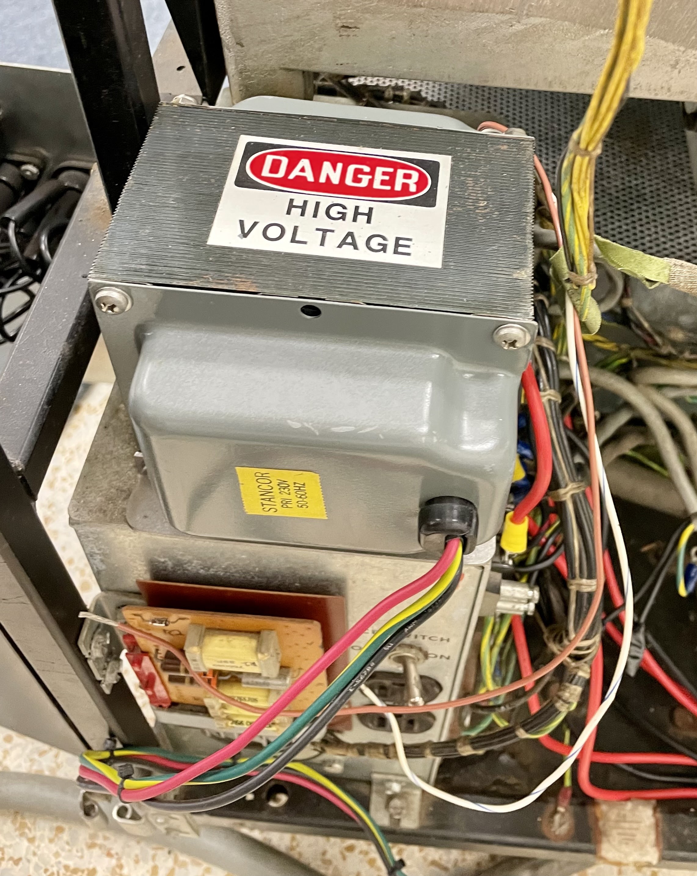
Transformer T2 provides 115VAC power for a limited number of loads in the 1130 computer - incandescent lamp power supply, selectric printer motor, customer usage meter and future expansion with peripherals that have 115V requirements. The Stancor transformer at 750 VA capacity is suitable for this.
 |
| 750VA capacity stepdown transformer |
I decided to mount the transformer right on top of the AC power distribution box, in a space that IBM has used for similar transformers. I drilled some holes and bolted it down well. The wires were trimmed and had ring terminals applied so that they could be wired into the terminal block where T2 connects.
 |
| Transformer being mounted above AC distribution box |
WIRED IN THE REPLACEMENT TRANSFORMER FOR 40VAC FOR USAGE METERS
The small transformer inside the Customer Usage Meter power supply had self-destructed due to being fed 230V across its 115V taps prior to arriving at my facility. When I corrected the wiring transformer succumbed to its prior injuries, emitting some magic smoke in the process.
 |
| Post-smoke view of the old transformer |
I sourced a suitable transformer to produce 40VAC which is what the usage meters require. It was slightly larger but I could fit it in to the housing and began to wire it into place. This power supply also includes some relay boards that switch between the Customer and the CE meters based on the setting of the CE keyswitch.
 |
| Replacement transformer for 40VAC |
It also runs the meter only when the processor and peripherals are active (the Run condition is on). The small board with the relays and its wiring will be replaced in the housing and have the transformer output connected, just before I remount the power supply box inside the 1130 chassis.
 |
| Wiring transformer into the power supply housing |
No comments:
Post a Comment