CAREFULLY CHECKING THE 1053 EMULATOR BEFORE USE
I designed and built an emulator to plug into the 1130 for when the console printer is not operational. It is shared on Github as https://github.com/cclaunch/PC1053 which I am updating based on this checkout and subsequent testing with the computer.
I am not sure if this had been plugged into my IBM 1130, it may only have completed checkout with a test driver subproject. Any errors in my implementation are likely mirrored in the test driver, thus this warranted some careful validation before I will turn on power on the 1130.
The first step was to verify from the 1130 ALDs that the connections on the SMS paddle cards are the signals I believed they were. I then beeped out these to the emulator to be sure I wired them to the intended pin of the Arduino or the intended terminal of the relay boards.
This design makes use of the open collector gates that IBM uses in the 1130 to drive the solenoids of the real 1053. These work fine with the pullup resistors built into the Arduino, thus I can directly hook these inputs to the Mega2560.
I fired up the emulator without hooking it to the 1130. This let me inject various signals as if the 1130 were emitting them by simply tying that SMS paddle pin to ground. I verified that the relays and the signals they connect were in the proper idle state, including reporting that paper was now in the typewriter.
All appears good, so it was time to connect this to the live 1130 system and begin debugging both my emulator and the device controller circuits inside the 1130.
HOOKUP AND USE WITH THE 1130 - SOME COMPLICATIONS
The 1053 connects to the 1130 with three SMS paddle cards, two for signals and one for power. SMS cards have 13 fingers on the end of a phenolic printed board, labeled A through R from left to right. IBM named the two signal connectors PF1 and PF2, while the power connector is called PP1.
With three otherwise identical SMS sockets, it would be important to get the proper paddle cards in the proper sockets. This is nothing unusual - nothing blocks putting an SMS logic card into a 1401 system in the wrong place, just as nothing stops someone from putting an SLT card in the wrong slot of a compartment on the 1130.
However, it appears someone was unduly concerned, as IBM took extraordinary steps to protect against inadvertent misconnection. The power paddle card fits into a bank of sockets for power delivery that has a heavy metal bar spanning the H finger position of all sockets. Thus, the paddle cards for power have to notch out the card where the H finger would sit so that it can slide in, otherwise it is mechanically blocked.
 |
| 1053 power paddle card with notch |
I can understand a bit why the power sockets need protection - there is 230VAC, 115VAC, 48VDC and 12VDC delivered across those fingers which would be a bad thing to deliver to logic cards or the signal paddle cards. However, IBM didn't stop there. They could have put notches in different positions of the two paddle cards and their corresponding sockets, but they did not. Instead, they converted one of the two paddle cards to a hanging SMS socket.
That spoils the purity of the SMS based signal connections. These are used for various peripherals - the 1053 printer, the 1134 and 1055 paper tape devices and the 1627 plotter. The block for these signal connections either has sockets installed or blank spacers for devices that are not configured on a particular system. The cards push into the block from the front and the sockets or spacers are all held down by metal rails which are bolted together at the ends.
Except . . . the 1053 signals are a pair of reversed connectors - one socket and one paddle card on the CPU side and one paddle card plus one hanging socket for the 1053 side. One can't simply pull the socket off the card, instead you must remove the metal bars, take apart all the sockets and spaces, thus freeing the socket that is attached to the 1053.
 |
| Signal cables PF1 below and PF2 above |
Since these two blocks for SMS connections are down inside the bowels of the machine, behind the built in disk drive and just behind power supplies, you must swing out the logic gates and crawl inside the machine to connect or remove these cards.
I now have an answer to my question of whether I had ever connected the 1053 Emulator to my 1130 system. I could not as I built the emulator with two paddle cards for signals and a regular power paddle card. No notch in the power card. No socket on the PF2 signal line, just a paddle card.
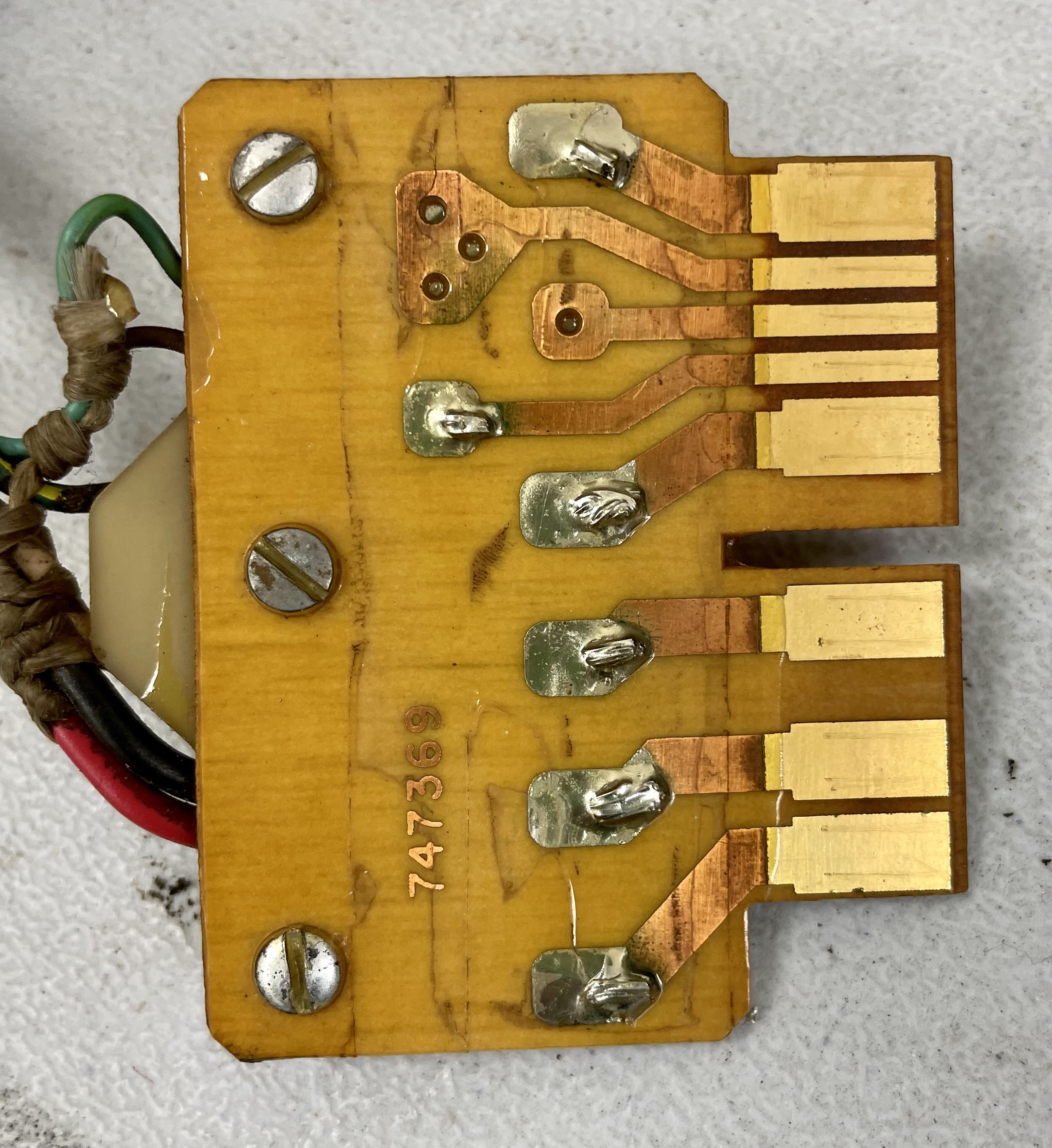
 |
| Emulator with paddle cards for both PF1 and PF2 |
MAKING CORRECTIONS TO THE EMULATOR TO PERMIT CONNECTION TO THE 1130
I used a hacksaw and cutters to open a notch where the H finger was on the power paddle card, allowing it to fit into the 1130's SMS power connector block with its blocking metal bar.
I found my spare SMS socket, one designed to take push on clips rather than wire wrap or solder. It took quite a bit of heat and technique to solder wires to those wide bars but I completed that, then soldered those wires into the paddle card for PF2. It is a bit clunky, but I can insulate and tie up the paddle card part and use the socket for the connection to the 1130's card.
If this were going to be a regular peripheral connected to 1130 systems I would hunt down a proper hanging SMS connector and wire it up to the emulator, doing away with the paddle card and funny socket extender. However, I see this as a device to be used for intervals where the 1053 itself is off the machine being serviced, to be removed once the console typewriter is back in service.
No comments:
Post a Comment