KEY ELEMENTS OF THE MODIFICATION I NEED TO VERIFY
In order to flip the drive between its normal mode accessing real cartridges using the read/write heads and the virtual mode where the heads stay above the surface, I have to interrupt the solenoid that pushes the heads downward to the disk surface. I also have to make the equivalent connection to the Heads Loaded microswitch which is pushed by the end of the pivot arm when the solenoid is retracted.
IBM SLT logic uses some oddball voltages that can cause damage to someone naively connecting logic circuits which are based on the normal 3V logic high level. Switches are debounced by applying as much as +12V and when opened, the junction is pulled down to a -3V level. Some of the solenoid related circuits are at +48V not 3V.
This is why I wanted to beep out the wiring, verify exactly how it is connected, and later to measure the voltages present in both logic low and logic high states. My eventual connections to circuitry I design has to accommodate the realities and work properly.
I will be grabbing quite a few logic signals that are commands from the CPU to the disk drive requesting arm movement, read or write signal activation and similar actions. Too, there are signals that are coming from the drive such as the sector marks that are essential for me to receive. I need these in order to model the position of the heads over the cartridge such that I can substitute virtual data for what the heads would have read. Finally, I need to know when the drive tried to load the heads on the physical disk surface so that I can fake the Heads Loaded signal to make the drive ready for I/O.
MECHANICAL ISSUE AND SOLUTION
One minor snag I encountered in my scheme was the blocking of the disk arm by the pivot plate that would load the heads onto the surface. If the plate doesn't pivot, keeping the heads high over the surface, then the arm can't seek in and out due to the physical interference.
My solution is to add a small bracket that slightly moves the pivot arm from its current rest position. It won't move far enough to begin pushing the heads down, but it will have cleared the interference so the arm can move back and forth. This bracket will bolt onto the Heads Loaded microswitch bracket.
My modification switches the -Pick/Hold logic signal from the solenoid wire to an Arduino pin, when the switch is set to virtual 2315 mode. It also disconnects the +Heads Loaded signal from the microswitch and instead routes it to a different Arduino pin. Thus, the Arduino will see the command to lower the heads and will respond indicating that this action has been accomplished, but the solenoid never actuates, the heads never lower and the Heads Loaded microswitch never activates.
EXTRA WIRE FROM THE HEADS LOADED SWITCH I WILL BYPASS
The schematics for the disk drive are intended for two purposes - either for the drive installed inside the IBM 1130 processor cabinet, or when the drive is in an external enclosure sold as the 2310. The schematics are drawn for the 2310 with some notes indicating what wires are not connected for the internal disk case.
One such situation is with the Heads Loaded switch. This switch is a SPDT microswitch that has Ground on the armature and is connected to the +Heads Loaded signal line on the Normally Closed contact. The Normally Open contact shows a dotted line that is listed as existing only for the 2310 installations.
However, there is a wire connected there! The +Heads Loaded signal line is connected to the usual SLT logic gate, which is a set of diodes whose common junction is elevated. If any diode is connected to ground or any low voltage that pulls the common junction down, the gate sees that a logic low input. Lack of current through the diode is, by default, a logic high level even if the voltage on the remote end is an open circuit.
.jpg) |
| Heads Loaded should have nothing on the N/O contact |
When the Heads Loaded microswitch is activated, it will disconnect ground from that signal line I care about but also makes a connection to ground for the other wire. Until I knew where it went, I couldn't be sure that my modification would work as intended, since the other wire will not be connected to ground when the Arduino handles the virtual head loading.
With some tracing and interpretation of vague comments on the ALD schematics, I realized that this wire runs from the Head Loaded microswitch to a terminal block at the front of the machine, but that the wire is not connected anywhere else. On a 2310, that terminal block slot would have a wire hooked further to a lamp on the 2310 cabinet that lights up to indicate when the heads are loaded. Therefore, my scheme works as far as this is concerned.
DISK DRIVE MOTOR START SWITCH NOT WELL DOCUMENTED
Another mystery from the schematics is the lack of a Motor Start switch. The 2310 has two pushbuttons, Start and Stop, that are not implemented for the internal drive case. These are SPDT switches, one that is normally open which triggers the K1 start relay and one that is normally closed which, in concert with relay contacts, keeps K1 active until the Stop button breaks the circuit to make the relay drop out.
 |
| Pushbuttons Start and Stop not implemented with internal drive |
As far as the schematic is concerned, there is no mechanism to start the motor or turn it off for the internal drive case. I see a DPDT switch on the front of the machine that I know will cause the motor to stop and start. However, I am not sure how it is wired. It could be wired the same way as the two independent Start and Stop pushbuttons of the 2310, but I will have to beep it out to be certain.
Schematic pages XK111 shows the switch, with its wires listed as going to XB101, whose diagram lists them running to the main disk schematic pages XA101. However, the names on the lines for XB101 don't match anything on XA101 nor is there any sign on XA101 that signals come to it from the 1130.
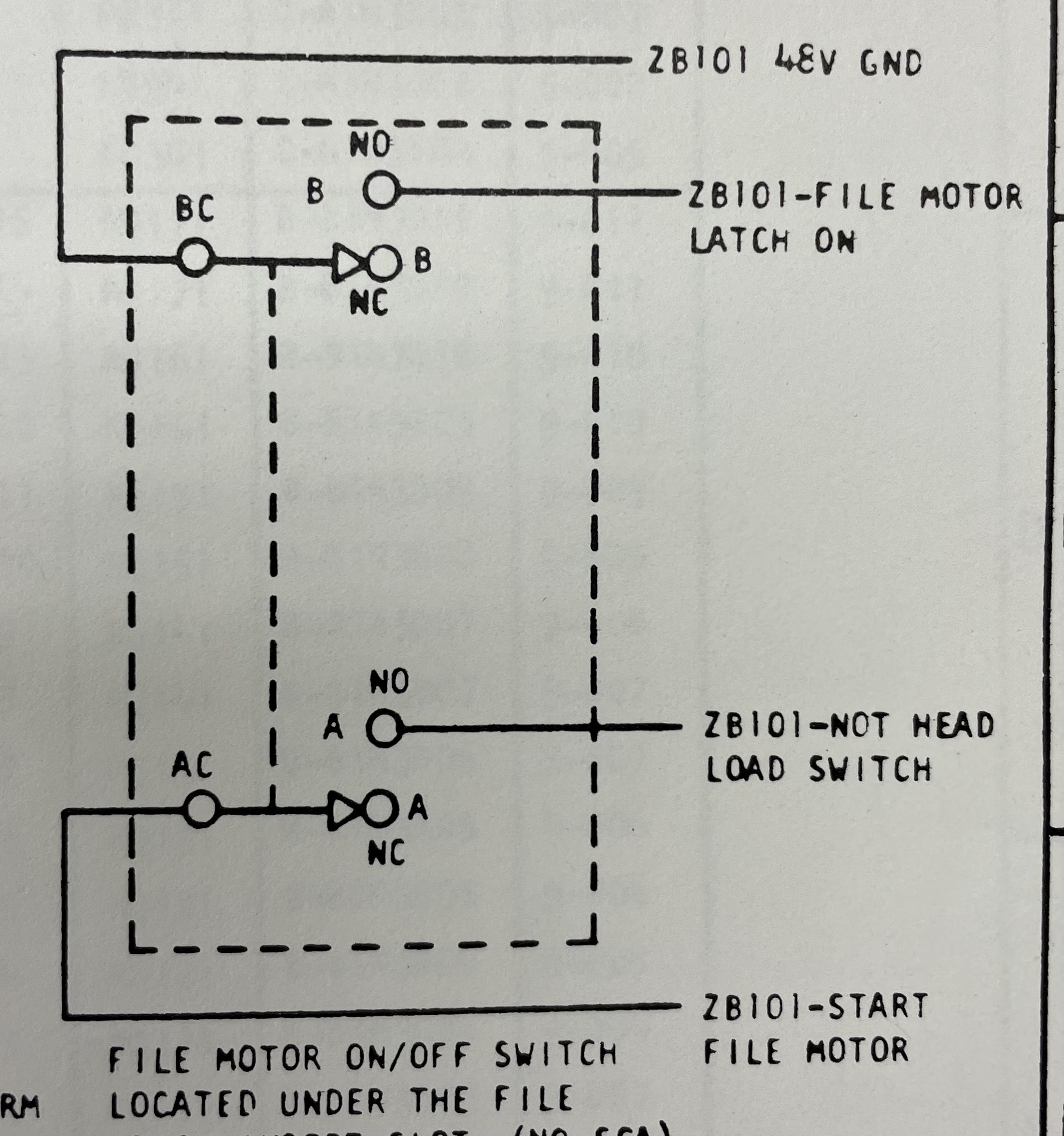 |
| XK111 shows switch hooked to XB101 |
 |
| XB101 shows lines hooked to XA101 |
I believe this is all consistent with the hypothesis that the one DPDT is set up to replace the two independent SPDT pushbuttons of the 2310. This actually does not impact my planned modification, it is more of a minor mystery I want to clear up.
No comments:
Post a Comment