SHORT SESSION TODAY
Today is the due date for filing individual income taxes in the US. I had prepared the taxes a few days ahead - it was pretty complex with the move between states, sale of the house and other events - and attempted to electronically file Friday night.
The return was rejected by the IRS, claiming that another return has already been filed under my taxpayer ID number. This is probably some kind of fraud where someone filed a return asking for a refund, claiming very little income. I have to deal with this, however.
I put a freeze on my credit agency files to protect against someone using the same identity information to attempt to sign up for credit under my name. There was no recourse other than to file by mail, including an affidavit that identity fraud was involved in the 'prior filing' they mentioned. This involved printing scores of pages of forms, signing and putting it all in a large envelope.
The state return to California also had to be filed by mail. This was even more pages printed, both the CA forms and a copy of my federal filing, in its own large envelope. For reasons too arcane to cover here, California won't accept a check from me thus I also had to send an electronic payment to match the amount due.
This morning we had to visit the post office, ensure the postage was correct and mail it off on the due date. From there, our overly shaggy dog had an appointment for grooming that extended into the mid afternoon.
CHECKING THE PRESUMED CONFIGURATION BY LOOKING AT SMS PADDLE BOARD
The 1130 has a small metal plate that holds SMS sockets where various peripherals are connected via SMS paddle boards. The first two positions on the plate are assigned to the 1053 console printer, the remainder are used for the 1134 paper tape reader, the 1055 paper tape punch and the 1627 plotter. There were no sockets or wires except for the first two positions, which proves that this machine did not have 1134, 1055 or 1627 attached.
CHECKING PRESUMED CONFIGURATION BY LOOKING FOR ASSOCIATED SLT CARDS
I swung out gate A and opened compartment A1 to check for the cards that are associated with the 1231 Optical Mark Reader. On my own machine, these card positions are empty but on the 1130 I am restoring the cards are all in place for the 1231 controller logic.
With all these checks, I can now confirm that this is an IBM 1130 model 2B, 8K core at 3.6us memory cycle time, featuring the 1053 printer and keyboard, the 1442 reader/punch and a 1231 optical mark reader. It had no other peripherals attached or configured into the system.
BUILDING RESISTOR COMPLEX TO LOAD THE POWER SUPPLY
I soldered together the 1 ohm 10W ceramic resistors I bought to form 1 ohm blocks that can handle 40W of load - two resistors in series, plus another two in series, both pairs hooked in parallel. These four 1 ohm blocks are mounted on terminal blocks so that I can wire them up with heavy gauge wire in a few different ways.
If I hook just one set of resistors up, it draws 6A from the supply. Two sets in parallel bring the load up to 12A, three sets get me to 18A and all four together will draw the full 24A that the supply is designed to deliver.
 |
| resistor load complex to draw 24A |
I am almost done, I just need to cut and install the lengths of wire that allow me to select how many resistor sets are in circuit and that connect this load complex to the power supply.
UNWIRED THE AC TERMINAL BLOCK IN THE POWER DISTRIBUTION BOX
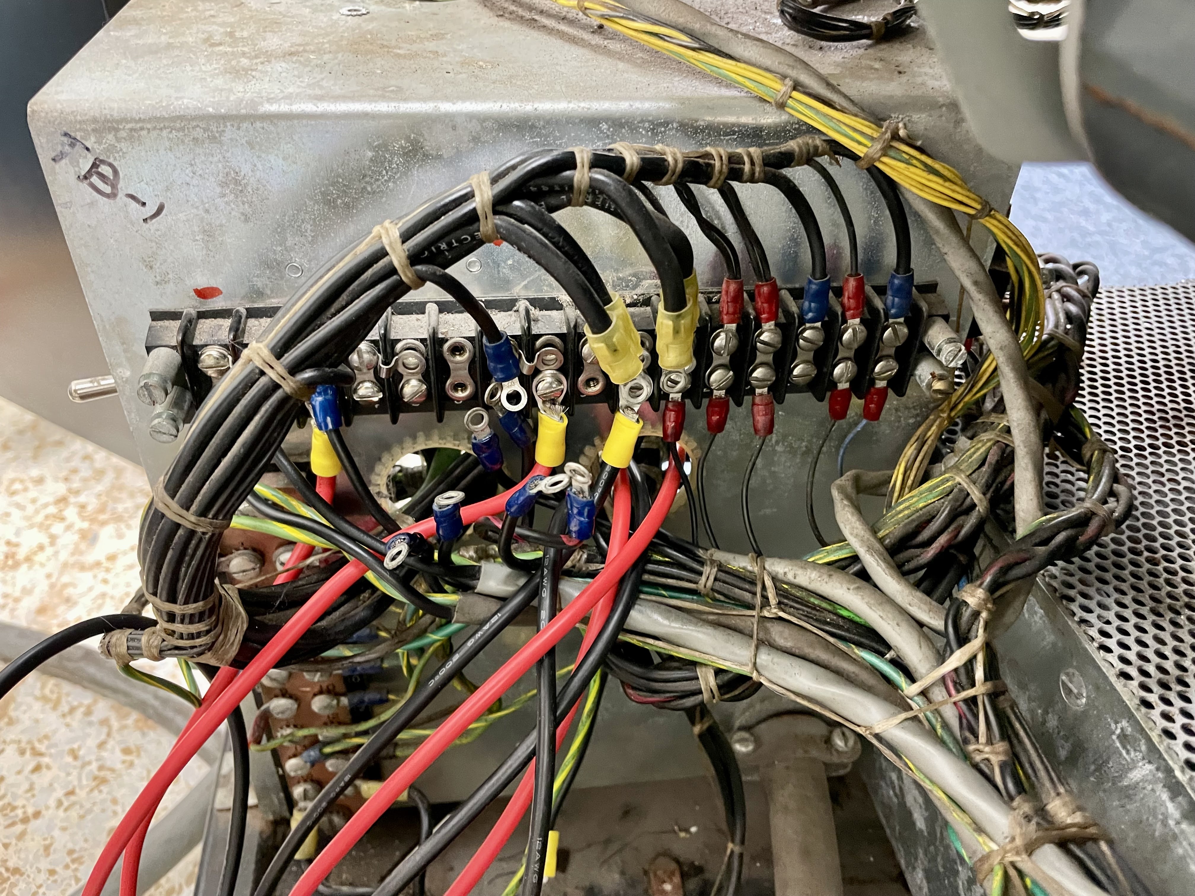
The terminal block TB-2 inside the power distribution box connects various fuses and power lines to destinations throughout the machine. Since I found several connections to be incorrect, I decided the best course was to detach all the wires, beep out the other end of each and then place them back on the proper location on the terminal block.
I had previously verified that positions 1 and 2 were properly wired, but encountered errors when I hit 3-4 and 5-6. I left the first two connected. These hook the fuses F1 and F2 to the raw DC power supply inputs. One of the inputs produces the +6, +3 and -3 supply raw power (the 6V raw power is close to 8V coming from this supply but is regulated down to +6V in the power supply I am repairing). The other input produces the +12 and +48V power which is used for functions such as driving relay coils.
All the other connections were removed from the terminal block strip and the screws placed in a plastic box. The next time I go to the shop I will find the proper wires by beeping and screw them down where they belong. When this is done, I still have to fix up the TB-1 terminal block that sits outside this box on the rear.
REPLACING ROMEX CABLE WITH MORE TYPICAL STRANDED WIRE
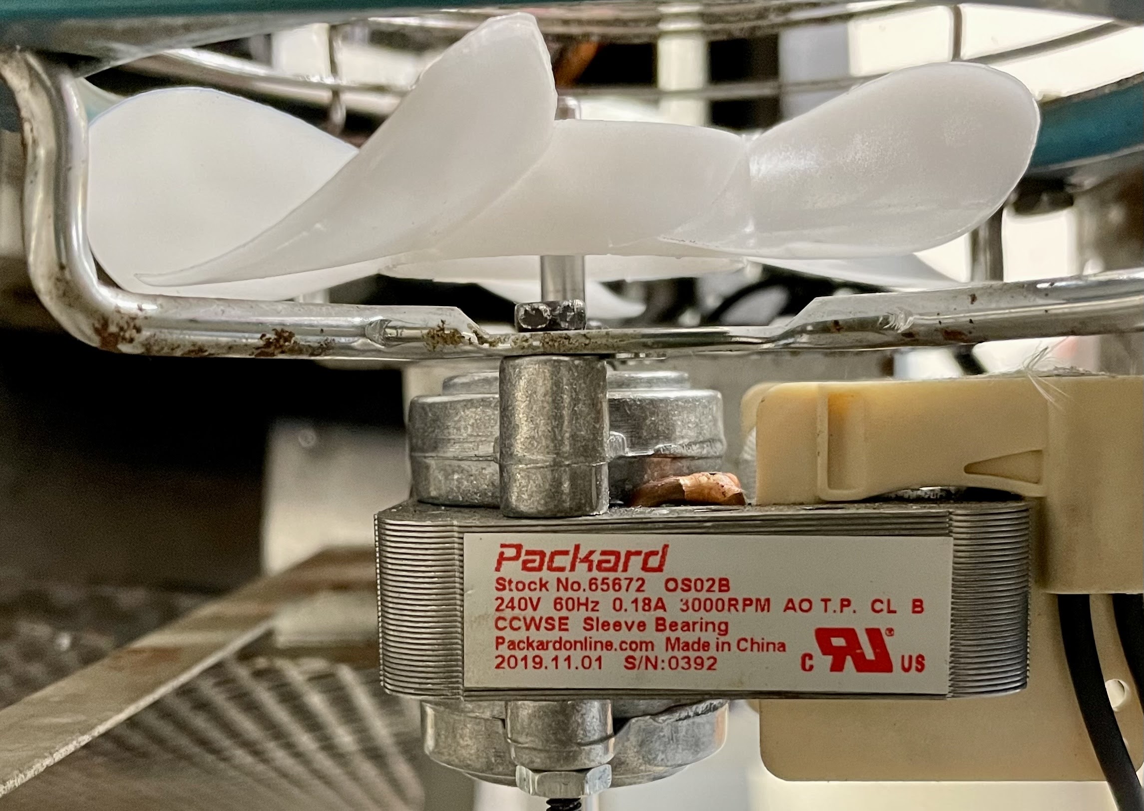
The two transformers that were replaced in this machine by a previous owner are both stepdown from the 230V supplied from the wall to 115VAC for various purposes. One of them supplies the convenience outlets on the 1130 and attached peripherals. The other supplies 115V for fans and other elements that require this voltage.
These substitutes were wired into the TB-1 and TB-2 terminal blocks using ROMEX cable, stiff solid conductor wires in a plastic sheath. This is the wire that is used inside walls in homes to distribute power to outlets and switches.
 |
| out of place Romex cable |
Inside the IBM mainframes, however, they didn't use solid conductor wire for power, the always used stranded wire covered in plastic. The 1130 has all of these individual stranded conductor wires laced into bunches that are routed like cables throughout the machine.
I am removing the romex and installing some stranded conductor wires that are similar to the ones used by IBM. This will make the machine look more consistent with the way it was originally constructed.