ROMEX REMOVED AND IBM STYLE WIRING INSTALLED FOR THE TRANSFORMERS
As I mentioned previously, the use of ROMEX style wiring is inconsistent with the wiring methods used in IBM mainframes in the 1950s, 1960s and 1970s. I decided to rewire with 12 gauge stranded single wires, wrapping them together with lacing much as IBM did during manufacturing.
 |
| Rewiring the transformers and lacing the wiring bundle |
REWIRING BOTH TERMINAL BLOCKS THAT HANDLE AC POWER CONNECTIONS
I have disconnected all the wires and am proceeding slowly and carefully reconnecting these in accordance with the original design. This will return the machine to the condition it would have had upon installation in the customer's location.
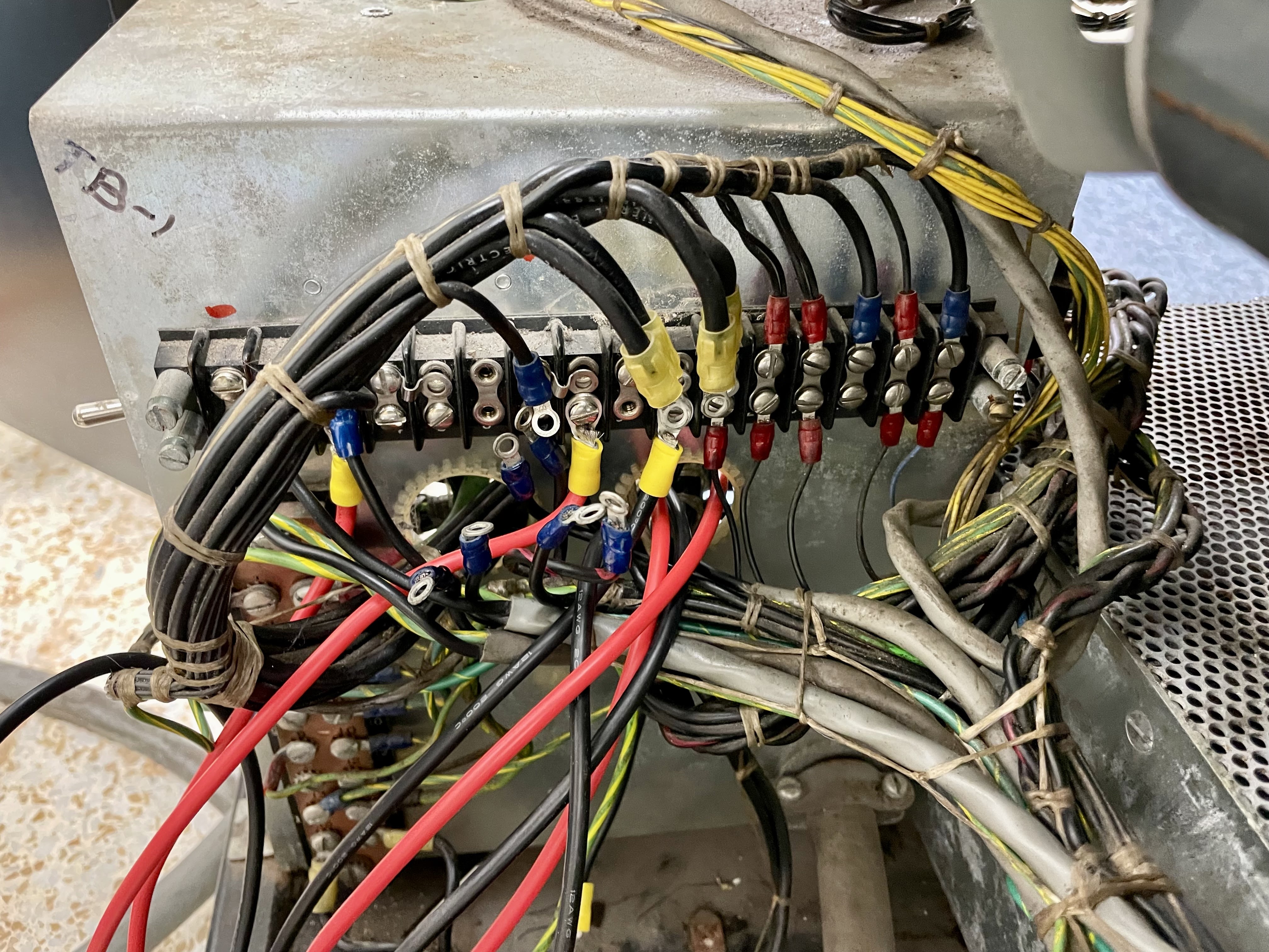 |
| TB-1 on rear of power distribution box |
 |
| TB-2 inside power distribution box |
LOAD TESTER FINISHED AND READY WHEN THE POWER SUPPLY IS REPAIRED
I completed all the cabling to produce my resistor complex to load down the 6V power supply for its final testing. This design has four segments, each draws 6A and they can be connected in parallel to draw 6, 12, 18 or 24A.
 |
| Each black lead adds a 6A load across the two long wires |
REMOVED AND VERIFIED VOLTAGE OF BLOWERS IN THE MACHINE
The fan assembly underneath the midpack voltage regulators was easily removable, which allowed me to see the dataplate on the fan motor and verify exactly what voltage these operate at. It is 230VAC.
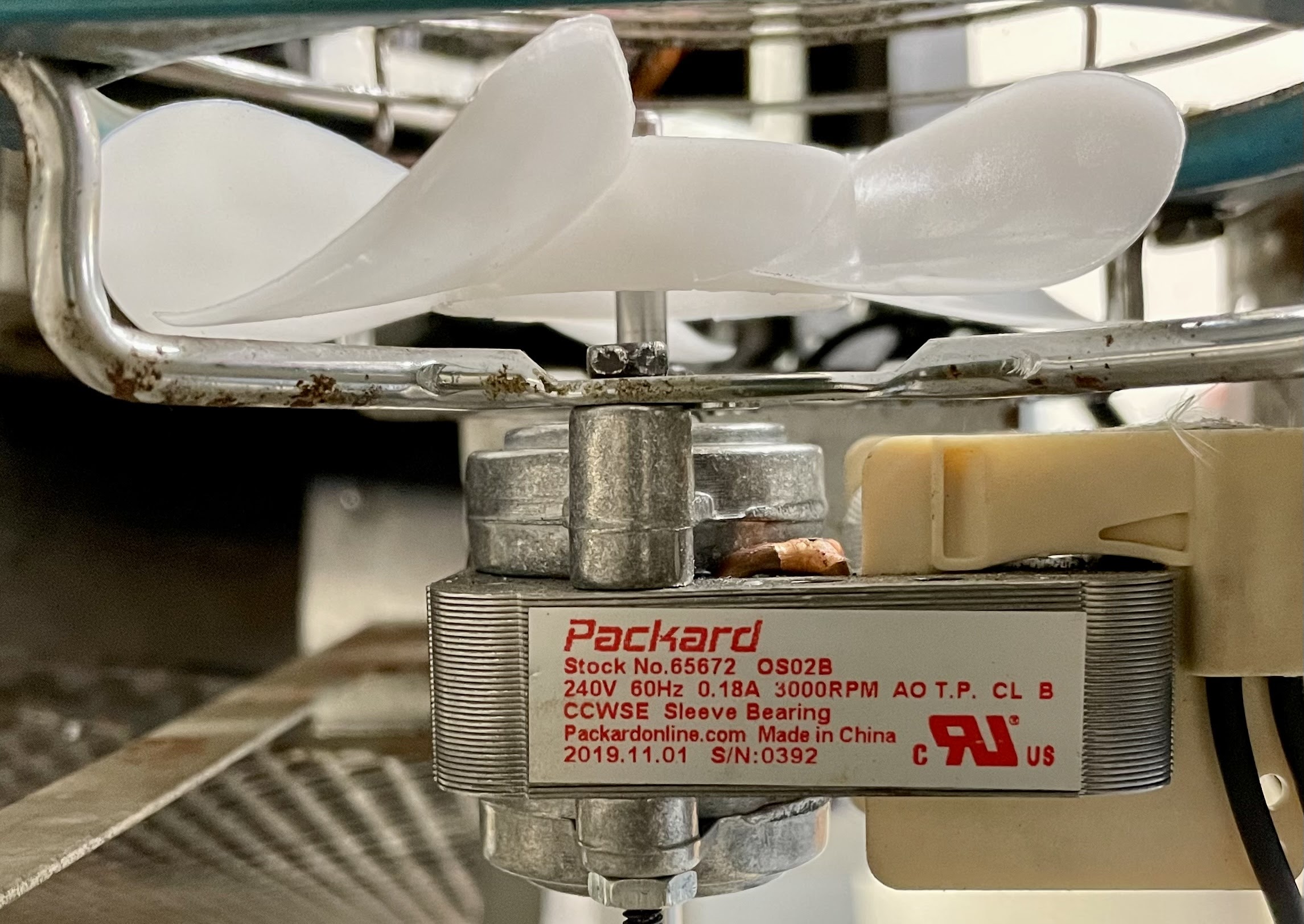 |
| IBM fan was replaced with a 230V version |
 |
| Removing fan assembly from under midpack regulators |
IBM thoughtfully designed the 1130 so that it could be connected to three different mains voltages - 208, 230 and 115. Most of the transformers inside power supplies had multiple taps, selected by moving wires and connecting jumpers to configure for the appropriate voltage.
There were a few items that were 115VAC only, due to limitations of the components themselves or to simplify IBM's supply chain. The fans that cooled the system were 115VAC, thus a stepdown transformer was included for any system that hooked to 208 or 230 mains supply. The motor in the selectric typewriter based 1053 Console Printer ran on 115VAC.
Finally, to standardize the tools that IBM deployed throughout their organization, all tools were 115V. To support use of these tools, IBM had convenience outlets inside most of their machines which let the field engineers plug in their tools regardless of the voltage levels used by the rest of the machine. A stepdown transformer produced the 115VAC for convenience outlets.
This machine had the original IBM fans removed and new blowers installed that ran on 230V, thus obviating the need for stepdown transformer T2 to produce the 115V to run cooling. However, the transformer is still used to deliver 115VAC to the 1053 printer and it supplied over the power cable to the fans on the IBM 1442 Card Reader/Punch. Fairly wasteful but this is the only way to drive the typewriter motor.
ISSUE SPOTTED WITH THE CONVENIENCE OUTLET TRANSFORMER T3
The second stepdown transformer T3 is provided to deliver 115VAC to the standard US style duplex outlet. IBM shipped only 115V tools to its FEs, who plugged them into these convenience outlets. Thus, any machine hooked to 208 or 230V mains had to step down the voltage to support the outlet. While a single transformer could have supported the fans, the typewriter motor and the convenience outlet IBM chose to isolate these so that if the convenience outlet blew a fuse it didn't stop the fans from operating.
While I was wiring these up and fastening them down so they didn't slide around inside the computer, I noticed that the data plate identifies the capacity of this transformer as 300VA. For a 115V convenience outlet, this allows only 2.6A of current, not the full 15A one would expect from a standard duplex outlet. IBM configured the fuses for the convenience outlet transformer at 6.25A to the primary of T3, which supports 12 1/2 A or more at the outlet. I am going to drop the fuse used for this circuit to 1 4/10 A as that will match as closely as possible to the capability of this substitute transformer.
PLANNED TO REWIRE SLIGHTLY TO HANDLE THE 230V FANS
Because of the use of 230V fans, they must be hooked to different locations than originally designed. The factory shipped systems had six positions on the terminal block assigned to the 115V output of transformer T2. That was hooked to the fans in the logic gates, the fan circuits to peripherals such as the 1442, and to the SMS based power that feeds, among other devices, the motor of the console printer. Each set of three positions is jumpered together and hooked to one side of the T2 transformer output.
With metal plate jumpers, we have the transformer hooked to one terminal and the other five available for fans and other power destinations. The 230V supply comes out of the power distribution box and hooks to two pairs of terminals. Each pair (7&8 or 9&10) is jumpered together. The input power to transformer T2 is fed from these terminals. They also provide power to most of the fuses on the distribution box and provide 230 to circuits for peripherals such as the 2501.
The four terminals on each pair for 230V can't easily sustain another three connections each for the fans. Since the fans are not going to be connected to the T2 output any more, I reassigned some of the terminals on the strip. Now, terminal locations 1 and 2 will be jumpered by wire over to the 230V on 7&8, while terminal locations 5 and 6 will be wire jumpered to terminals 9&10. I removed the metal plates bonding these to terminal locations 3 and 4, which remain assigned to the 115V output of T2.
Terminals 3 and 4 carry the 115V to the SMS connector for the 1053 Console Printer motor, as well as to the fan power pin for the 1442 Card Reader/Punch.
 |
| Jumpers to bring 230V over to the fan screws on terminal block |
While this sounds simple to execute, the challenge is that IBM's cables are carefully cut to length and laced together so that each wire end naturally reaches its destination terminal on the block. Because I have moved some things around slightly the wires don't fit so naturally to their new destinations.
Unless I'm mistaken, these fans aren't particularly expensive or unique. Wouldn't it be a better long-term solution to simply swap the fans out for ones with the expected voltage, especially if it was originally all 115V?
ReplyDeleteI thought of that but the cumulative draw of seven fan motors plus the 1053 motor would blow past the measly 300VA capacity of the T2 transformer. In this case, to restore it fully would require finding a much beefier stepdown transformer as well as swapping out the blowers.
DeleteAhh, that makes sense then, thanks for the explanation.
Delete