Some conditions are tested for by the circuitry in the Diablo and would result in a WriteCheck condition:
- WriteGate on but no write current
- Head current when WriteGate is off
- No Erase current when EraseGate on
- Erase current when EraseGate off
- Erase current through both heads at same time
- Write current through both heads at same time
- Voltage dips below 13.5 V
Presumably, my problems in the Diablo drive don't include those situations, or I would have an immediate WriteCheck. I do have the sporadic situation where the drive powers down, flashing both FileReady and ReadyToSeek/Read/Write signals a couple of times.
To recap some other symptoms observed so far:
As noted yesterday, the voltage on the center tap of the upper head should be about +1V when selected, -1V when not the selected head and +14V when writing. I confirmed both -1 and 14V levels, but the selected level is noiselike at dozens of millivolts rather than roughly 1V.
Also noted yesterday, when I measure the output of the differential amplifier responding to the read head output (testpoint 1 on the board), I see a dozens of millivolt noiselike signal when reading the sectors on cylinder 0, even after I write, but I get multivolt wide swings on any other cylinder.
When I write sector 0, I see the WriteGate activate and the proper pulses delivered to the WriteData&Clock line on the terminator. Reading back the sector still has the essentially erased output, millivolt noise, but no signal swings.
Therefore I need to check step by step to verify that my write signal is delivered to the heads properly. It would be easy if I had an extender card to push card J10 back giving me direct access to the various probing points, but to use it I would also need an extender for the cable from the read/write heads. Don't have either.
First new observation - I set the scope to trigger on the WriteData&Clock signal coming from the fpga and put the other probe on testpoint 1 to observe the flux reversals. I saw an odd dip in the midst of each transition, and the pattern for when I had a 1 bit wasn't correct either.
 |
| Top line shows flux reversals I should see on testpoint 1 |
 |
| Test point 1 with odd decay in each signal |
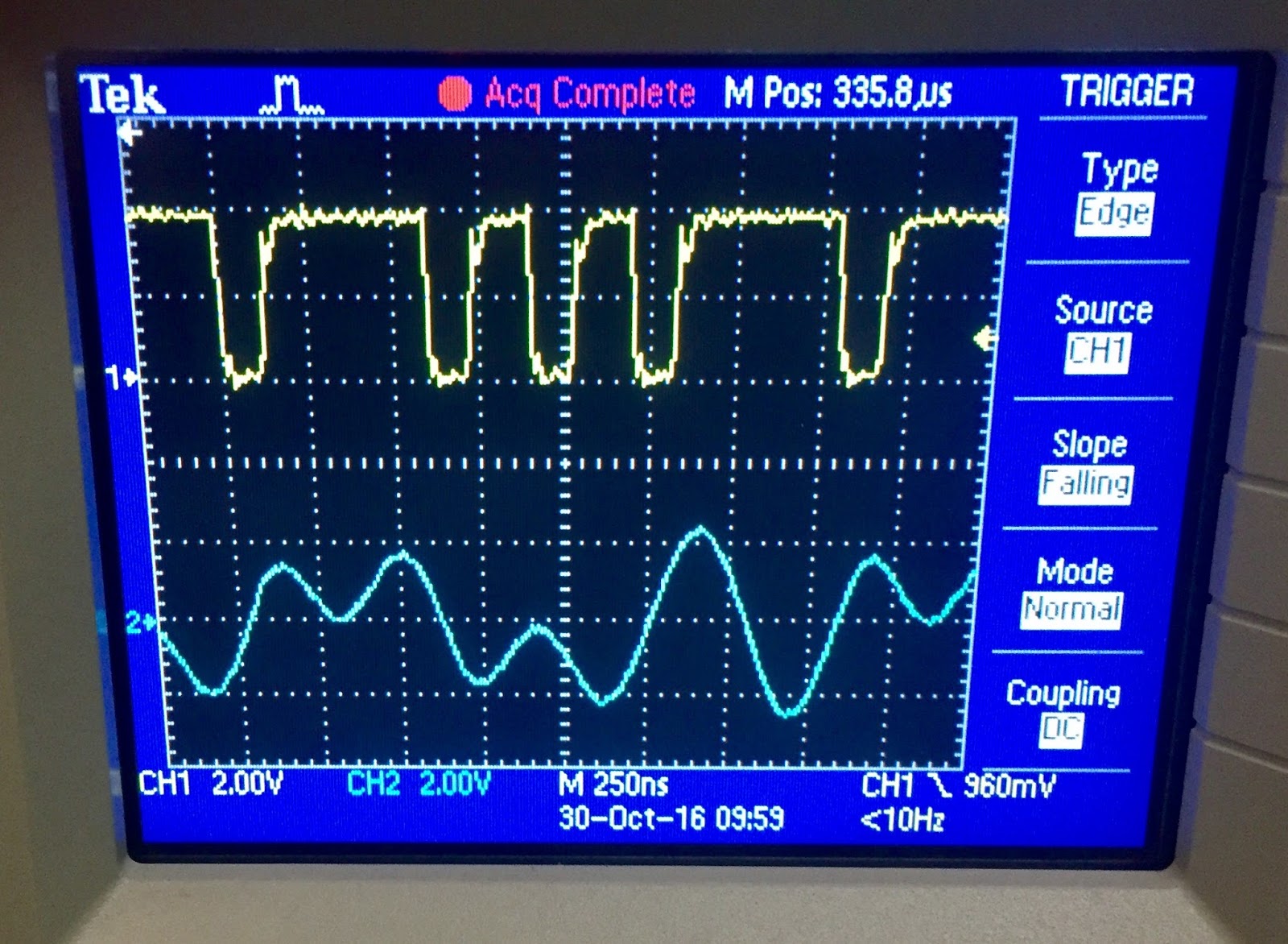 |
| Clipped signal at TP2 seems almost the reverse of what I should see - dips when bit is 0 |
 |
| I am writing multiplexed pulses correctly, but write current might be wrong |
The testpoint 1 is at one output of the differential amplifier on the read head. The trace without the dips would be seen when reading this sector. Since the Alto docs mention leaving ReadGate on during a write and observing the written bit stream, I presume that the testpoint 1 signal should look legitimate, without the dips. The dips are bound to cause false recognition of both clock and data bits.
Here is the sequence of observations that must be made to determine from where the malfunction stems:
- Scope on output of the D flipflop that causes flux reversals, triggered by WriteData&Clock
- Scope on inverse output of the D flipflop triggered by WriteData&Clock
- Scope on head bus A, triggered by WriteData&Clock
- Scope on head bus B, triggered by WriteData&Clock
- Scope lower surface head to verify its +1, -1 and +14V behavior
I set up for test 1 and 2, putting micrograbbers on the flipflop pins. Both sides of the flipflop show transitions just as expected. I have labeled these A and B respectively in the closeup of the schematic below.
 |
| Testing at Q and notQ output of D flipflop |
 |
| Expected signal at point B (notQ) |
 |
| Signal at point A (Q) |
Next up is to scope on head bus A and again on head bus B. The bus A signal looked reasonable, although it only swung down to +5V from +14, not sure if that is correct. On to look at head bus B to compare.
 |
| Head bus A signal |
The other bus looked similar, evincing swings from 5V upwards, but I can see that the upper half of the bus A waveform is clipped off compared to the bus B version. I will now look at the bus A path for components that might cause this distortion. B is nicely symmetric while A is not.
 |
| Head bus B signal |
The above two views of bus A and bus B are taken from points C and D of the schematic excerpt below. Next I moved over to points A and B to see the drivers of the two bus lines.
 |
| Probe spots for head bus A and B |
The signals at points A and B above both look good, equally symmetric. Whatever is clipping the peaks of the signal at point C (my Head bus A signal above the schematic) occurs on the right hand side of diode B81.
 |
| point C - bus A driver |
 |
| point D - bus B driver |
Now, I move to figure out what is clipping the tops of the bus A signals once it moves through the diode D81 I will repeat the view of points A and C, the ones that showed clipping, but while writing on the lower surface (head 1). This will eliminate the head itself as a causative agent.
I ran the tests and saw no clipping on the head bus A or B when writing on head 1. I then switched back to head 0 (the upper surface) and captured bus A again. Now I am confused - this time I saw no clipping.
 |
| Retest of point C on upper head - this time no clipping |
Still, once the sector was written, when I tried to read it back the signal was like noise, not the magnetization level I would expect. At this point, I am still mystified.
Musings - could the voltage swing on the bus be too small to flip magnetic domains? Seems unlikely given how symmetric the behavior is. Is something wrong with the erase winding or driver?
One final test of the evening - monitoring the erase driver input to the drive transistor, just to be certain that it thinks it should fire. I suppose one cause for the lack of discernable transitions when reading is that the write is actually not doing an erase, thus layering so many transitions that there is no clear signal to read.
 |
| Probing point to check erase operation |
 |
| Erase driver definitely turning on |
Now that I see the drive voltage firing up for the erase driver, and had previously seen a current draw curve that was similar to this, I have to again assume that erasing is working properly. I remain mystified as to what is happening on the drive.
Oddly, after I write the sector, I see checksum errors on the label and data record, but not header record when I try to read it back. Since the write is producing its own checksums, that is definitely odd.
No comments:
Post a Comment