INSTALLING POWER SUPPLIES AND WIRING THEM INTO THE SYSTEM
I closed up the DC Supply, the unit that provides the raw DC to the regulated power supplies like the one I am repairing. I slid it into the machine and began to wire up the two terminal blocks - the AC inputs side and the DC outputs, essentially.
.jpg) |
| DC Power Supply - raw DC outputs |
 |
| Inserted in place, ready to wire up |
 |
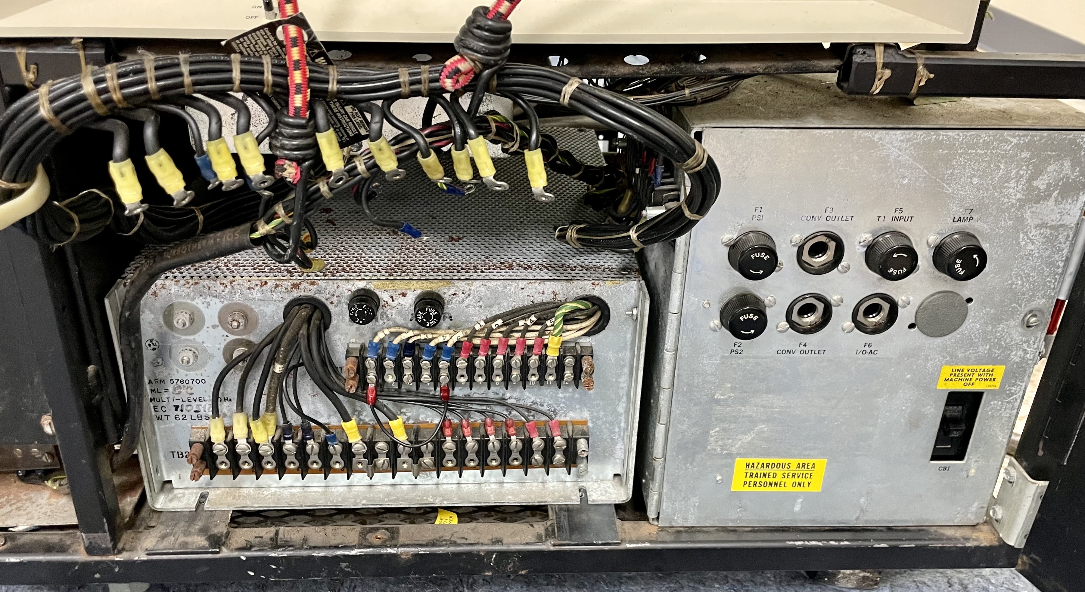
| TB-1 completed, TB-2 at bottom to do next |
 |
| TB-2 completed, plastic safety cover on TB-1 but not yet TB-2 |
I then put the +6V Regulated Supply into the chassis and began wiring it up to the input from the DC Supply. I did not connect the load side - the logic circuits that are connected to the 6V rail.
 |
| 6V Regulated Supply ready to insert |
TEST RESULTS WITH 6A, 12A, 18A AND 24A
With the power supply mounted in the 1130 chassis and its raw 16.5V DC input connected, I wired it to my resistor complex which lets me select 6A, 12A, 18A or 24A loading. The supply held up great, although with a bit of sag in voltage when I hit its full 24A rating. Since my expectation is that this 1130 will be closer to 15A maximum load and the average even less, I thought I was good to go.
 |
| Resistor complex to load up the power supply |
ADJUSTING +6V AT RAILS OF BACKPLANES IN 1130, BREAKER TRIPS
I removed my resistor complex, wired in the 1130 logic load. I first checked the resistance of the 6A load side and found it at 3.8 ohms, which means that the idle consumption will be teeny. With everything tidied up, I flipped on only the 6V supply, with a voltmeter on the logic backplane side to sense the delivered voltage, then powered up.
What I expected was minimal load and an opportunity to adjust the 6V rails to the middle of the target range, right on 6.00V. Instead, I heard the breaker click off immediately. This was disappointing indeed. Out came the supply and over to the bench to figure out what else had failed.
MACHINE STILL GOOD ON BENCH AND AT HIGH LOAD - HMMMMM
With it hooked up and the 4A electronic load active, I powered it on and it was behaving properly. Perhaps it was a load based issue, thus I hauled it back over, slid it into the chassis and wired it up again with my resistor complex to give it high load.
It passed again! On a hunch, I connected only the Common (ground) side of the 6V load to the power supply and powered up. Click. Immediate breaker popping. This is quite mysterious.
The DC Supply that gives us 16.5VDC raw input should be completely isolated from the Common logic side. It is dead simple, a transformer secondary wired to a half wave rectifier and a filter capacitor. No connection from either of the output lugs to anything else in the machine nor to any kind of ground. This should be completely isolated.
However, all is not well in the world of the 1130, since the mere connection of one wire that should have zero path to the DC input causes an immediate overload and shutdown. This is going to require some investigating to figure out what has gone awry, most likely over in the DC Power Supply box.
No comments:
Post a Comment