A reader of this blog pointed out an auction on eBay of a 360 model 40 front panel in good condition, designated as only for sale for local pickup by some from the bay area. Because these don't show up often, I reluctantly bid on it, which would have created another enormous project - building an fpga replica of the 360/40 processor that would power the panel. I had mixed feelings and thus am not upset that I was outbid. Back to the 10,000 tasks already in my queue.
1132 PRINTER RESTORATION
In order to free up, clean up and relube the rest of the print mechanism, I have some disassembly to do. I began removing screws to lift off the detent latch and restoring lever bars along with their attached levers. These can be rehabilitated once removed. It also gives me more access to the print cams, where I can evaluate the feasibility of cleaning and restoring the cam, attached dog and the associated detent link as it sits. if that seems unlikely, I will then remove the print cam assembly which actually involves removing the carriage and lots of the rest of the printing mechanism.
There are several sheet metal shapes in place blocking some access to the screws for the restoring lever screws and the print cam shaft. I have to remove or loosen these enough to tilt them away when I am accessing certain screws. I got partway through before the evening arrived and I went in for dinner.
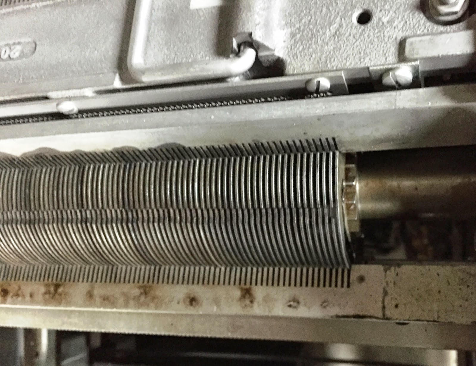
Later, I removed the top bar which was the cam detent assembly, moved it to the workbench and began to work in lubricant. I discovered the levers moved well enough but for some columns, there was noticeably less spring tension returning the bar to its idle position. I opened the chamber and boiled all 120 springs, working them in and out of their channels.
 |
| Detent assembly, the spring loaded levers should all be at extended rest position |
 |
| Pivot side of the detent assembly - unevenness very evident |
 |
| Closeup of sticky levers |
 |
| Little springs in their channels, pushing the detent levers outward |
The next bar to remove from the printing mechanism is a double decker bar that holds the restoring latches. I will pull that out and get all of those working freely too. Each of these bars has the tiny springs inside, thus I may find a few more springs that need replacement. I actually don't know if the spring issue is bad enough to cause printing problems, but I can make a determination with the bar back in place; if the cam doesn't lock into position on the weak columns, the spring needs immediate replacement, otherwise it might be a longer term restoration task.
 |
| Cam discs in top half, double decker bars hold restoring levers (bottom half of picture) |
I have enough room now to inspect the cams - a few are sticky but there is enough access so that I can get oil to all of them such that they will all rotate freely. The print wheels hang from a pivot that is directly accessible, allowing me to get enough oil in that I can assure they move properly.
 |
| Print wheel pivot points, one character on print wheels visible just above pivots in picture |
 |
| Cam clutch disks, dog latch rotating on side pushes into the fluted slots in shaft to spin cam |
Two mechanisms are still hidden and might force me to do more dis-assembly. First is the cam clutch latch which sits on the other side of the cams from where I am servicing them, and below the axis point too, thus directly behind the cam from my vantagepoint looking in on the machinery. Second is the dog latch with spring that is on each rotating cam plate - it needs to swing in and out if the cam clutch is to engage to print a column - but with them deep in between the parallel cams, any dogs that don't free easily may require dis-assembly of the entire print clutch/cam unit.
 |
| Clutch latches are directly under the cams - far side from this point. Dog latches are on sides of discs. |
This will take a few more days but so far I am satisfied with the progress I am making. It appears to be possible to get this assembled again and printing well, just by finishing this cleaning and lubrication work.
COMPUTER HISTORY MUSEUM 1401 RESTORATION
I meet a small group from the restoration team at midday and we went to work on various parts of the systems. One group had to disassemble and repair the punch on the German 1402 reader/punch as it frequently jams. We discovered some misalignment of parts and wear, which forced the team to tear down the unit quite a bit.
I did a quick replacement of two console panel bulbs that had burned out on the Connecticut 1401 system, then turned my attention to a problem the German machine has with its tape drives. The system writes a string of characters, for example 123456789 then backspaces and reads them back. The write completes with no error but the read returns 1337777 with check bit errors.
It seems that when you begin a record, any time a bit is on, it will stay on for the remainder of the record even if it should be off for that character. Thus, the 1 bit is on for the first character '1', then the 2 bit turns on while we still have the 1 bit active, so the '2' comes out as '3' (both 2 and 1 bits on). The '4' character turns on the 4 bit, making the 4 2 and 1 bits on for a '7'. This stays true until we get to character '8', which turns on the 8 bit but we still have 4, 2 and 1 thus a special unprintable character is returned for '8' and '9'.
I figured out how to turn on Bob Feritich's virtual tape drive, a bit of hardware that sits on the tape cable chain and acts like a 729 tape drive. We used that to write and read the pattern, still seeing the problem which confirmed to us that the issue is not in the tape drives but inside the electronics in the 1401. By the time I left, we were scoping various signals to determine what was happening. It seemed like the bits were coming in correctly from the tape drive but somehow corrupted after that point. I ran out of time and left, so unsure of what progress was made for the rest of the afternoon.
SAC INTERFACE FOR ADDING PERIPHERALS TO THE 1130
I looked over specifications of fast switching transistors and discovered one, the BVS52, that slashes the storage time impact on cutoff, allowing my original circuit design, sans bypass capacitor around the base resistor, to operate with less than 20ns delay from when the incoming 1130 signal drops until my transistor cuts off allowing the output signal to rise.
I placed an order with DigiKey for all the components for my new board and will, after a few tweaks of the design and verification of the Gerber code produced, send it off for fabrication. The oddity about my design is that I accomplished all the routing on the board using only top side copper traces, thus I wanted to convert the bottom side to a power plane rather than a signal surface.
For historical reasons, the files for the interior power planes of most boards are negative, meaning they describe the shapes that should be removed from the copper layer rather than a positive file like the top layer where each feature in the file represents copper to be left on the board. The fabrication site will invert the gerber file for power planes to positive. Since this is a step done by the processor, not inherent in the gerber file itself, there is the risk of an error with nonstandard use of the bottom layer
I want my bottom layer to be a powerplane will have copper poured across the area with small cutouts around all the via holes. I have to be sure that the gerber file will produce the right result, giving me the broad copper area with some holes, rather than metal rings around vias and a wide open area. I will have to inspect the detailed content of each gerber file to ensure it is interpreted reasonably by the board fabricator. I downloaded the protocol specification for gerber files, which are ASCII format files that are human readable.
I figured out how to get close to what I want, but it is complex to get the files the way the fab wants them. For example, I use OSHPARK to check out my files - they want the internal power planes to be positives not negatives. Have to regenerate the gerbers once again. I am much closer than yesterday, however, and with another hour of work I should be able to order my boards.
Having verified everything and carefully documented it all, I sent it to GoJGo.com where I had an urgent turnaround of ten copies of the four layer 6.5 x 3" board, silkscreen, solder masks, and automated testing of the result, all for $162 (plus $35 for DHL Express international shipment). I should have the completed boards back in less than two weeks, ready to assemble and then install.
DATACENTER SHED CONSTRUCTION
I picked up the epoxied together joint handle and installed it over the two breakers that cover my 240V single phase 20A circuit feeding the IBM 1130 system.
Having verified everything and carefully documented it all, I sent it to GoJGo.com where I had an urgent turnaround of ten copies of the four layer 6.5 x 3" board, silkscreen, solder masks, and automated testing of the result, all for $162 (plus $35 for DHL Express international shipment). I should have the completed boards back in less than two weeks, ready to assemble and then install.
 |
| Component view, one board hosts12 receivers and 12 drivers |
 |
| Top view of board, before it is covered by green solder mask |
 |
| Bottom view of board, copper ground plane plus green solder mask |
DATACENTER SHED CONSTRUCTION
I picked up the epoxied together joint handle and installed it over the two breakers that cover my 240V single phase 20A circuit feeding the IBM 1130 system.
 |
| Handle installed over pair of breakers for 240V circuit |
Carl, I hope everyone is as impressed as I at your willingness to break into the 1132 print unit. Only someone who's seen an 1132 or 407 can appreciate the uniqueness of this mechanical engineer's delight. I went looking for some kind of image to show the complexity of it. Here's what I found:
ReplyDeleteIBM1130.org has some harsh words to say about the 1132 design from a programming point of view:
http://ibm1130.org/hw/printers
On archive.org, which is now the home of bitsavers it seems, I found the 1132 parts catalog. The typewheel assembly is on page 78,
https://archive.org/stream/bitsavers_ibm1130fe1artsCatalog_7877055/127-0806-2_1132_Printer_Parts_Catalog#page/n91/mode/2up
I found the 407 parts catalog at the Pierce-Fuller collection site. (Paul Pierce is the guy who recently donated two tractor-trailer loads of old computers to CHM.) Scroll down to page 407-19 for a better picture of the typewheel assembly.
http://www.piercefuller.com/scan/ibm-124-0023-1.pdf?id=ibm-124-0023-1
Finally, also at Pierce-Fuller I found the 407 Maintenance Manual. Printer lube and adjustments starts about page 32.
http://www.piercefuller.com/scan/ibm-225-6110-6.pdf?id=ibm-225-6110-6
That manual makes clear that in the 407, printing depended on a rube goldberg mechanical nightmare called the Analyzer Unit, which did with mechanical parts what the programmer has to do during printer interrupts in the 1130. Just be glad you don't have that component to clean up!
Hi David
ReplyDeleteI have the parts catalog, maintenance and theory of operations manuals, which were helpful but far from sufficient to work on the unit. It takes a fair amount of intuition, exploration and sometimes backtracking in order to take it apart, fix it and put it together again.
The programming is indeed odd. When you tell the printer you want to print a line, it begins interrupting the 1130 as each new print character rotates into position in front of the platen. The program has to issue a read emitter command to find out what character is ready to print, then look over the target print line to find out which columns have this character in them. For each column of the print line, you set a bit to 1 in a fixed area of low core - the printer then fetches those words and fires the 'hammer' for the columns you selected. next character comes in, you do it again, over and over until there are no more nonblank characters in your intended print line. When done, issue Stop print which really means "don't interrupt me any more with print wheel characters".